This is the multi-page printable view of this section. Click here to print.
Talos Linux Guides
- 1: Installation
- 1.1: Bare Metal Platforms
- 1.1.1: Digital Rebar
- 1.1.2: Equinix Metal
- 1.1.3: ISO
- 1.1.4: Matchbox
- 1.1.5: Network Configuration
- 1.1.6: PXE
- 1.1.7: SecureBoot
- 1.2: Virtualized Platforms
- 1.2.1: Hyper-V
- 1.2.2: KVM
- 1.2.3: OpenNebula
- 1.2.4: Proxmox
- 1.2.5: Vagrant & Libvirt
- 1.2.6: VMware
- 1.2.7: Xen
- 1.3: Cloud Platforms
- 1.3.1: Akamai
- 1.3.2: AWS
- 1.3.3: Azure
- 1.3.4: DigitalOcean
- 1.3.5: Exoscale
- 1.3.6: GCP
- 1.3.7: Hetzner
- 1.3.8: Kubernetes
- 1.3.9: Nocloud
- 1.3.10: OpenStack
- 1.3.11: Oracle
- 1.3.12: Scaleway
- 1.3.13: UpCloud
- 1.3.14: Vultr
- 1.4: Local Platforms
- 1.4.1: Docker
- 1.4.2: QEMU
- 1.4.3: VirtualBox
- 1.5: Single Board Computers
- 1.5.1: Banana Pi M64
- 1.5.2: Friendlyelec Nano PI R4S
- 1.5.3: Jetson Nano
- 1.5.4: Libre Computer Board ALL-H3-CC
- 1.5.5: Orange Pi R1 Plus LTS
- 1.5.6: Pine64
- 1.5.7: Pine64 Rock64
- 1.5.8: Radxa ROCK 4C Plus
- 1.5.9: Radxa ROCK PI 4
- 1.5.10: Radxa ROCK PI 4C
- 1.5.11: Raspberry Pi Series
- 1.6: Boot Assets
- 1.7: Omni SaaS
- 1.8: talosctl
- 2: Configuration
- 2.1: Configuration Patches
- 2.2: Containerd
- 2.3: Custom Certificate Authorities
- 2.4: Disk Encryption
- 2.5: Editing Machine Configuration
- 2.6: Logging
- 2.7: NVIDIA Fabric Manager
- 2.8: NVIDIA GPU (OSS drivers)
- 2.9: NVIDIA GPU (Proprietary drivers)
- 2.10: Pull Through Image Cache
- 2.11: Role-based access control (RBAC)
- 2.12: System Extensions
- 2.13: Time Synchronization
- 3: How Tos
- 3.1: How to enable workers on your control plane nodes
- 3.2: How to manage PKI and certificate lifetimes with Talos Linux
- 3.3: How to scale down a Talos cluster
- 3.4: How to scale up a Talos cluster
- 4: Network
- 4.1: Corporate Proxies
- 4.2: Host DNS
- 4.3: Ingress Firewall
- 4.4: KubeSpan
- 4.5: Network Device Selector
- 4.6: Predictable Interface Names
- 4.7: SideroLink
- 4.8: Virtual (shared) IP
- 4.9: Wireguard Network
- 5: Discovery Service
- 6: Interactive Dashboard
- 7: Resetting a Machine
- 8: Upgrading Talos Linux
1 - Installation
1.1 - Bare Metal Platforms
1.1.1 - Digital Rebar
Prerequisites
- 3 nodes (please see hardware requirements)
- Loadbalancer
- Digital Rebar Server
- Talosctl access (see talosctl setup)
Creating a Cluster
In this guide we will create an Kubernetes cluster with 1 worker node, and 2 controlplane nodes. We assume an existing digital rebar deployment, and some familiarity with iPXE.
We leave it up to the user to decide if they would like to use static networking, or DHCP. The setup and configuration of DHCP will not be covered.
Create the Machine Configuration Files
Generating Base Configurations
Using the DNS name of the load balancer, generate the base configuration files for the Talos machines:
$ talosctl gen config talos-k8s-metal-tutorial https://<load balancer IP or DNS>:<port>
created controlplane.yaml
created worker.yaml
created talosconfig
The loadbalancer is used to distribute the load across multiple controlplane nodes. This isn’t covered in detail, because we assume some loadbalancing knowledge before hand. If you think this should be added to the docs, please create a issue.
At this point, you can modify the generated configs to your liking.
Optionally, you can specify --config-patch with RFC6902 jsonpatch which will be applied during the config generation.
Validate the Configuration Files
$ talosctl validate --config controlplane.yaml --mode metal
controlplane.yaml is valid for metal mode
$ talosctl validate --config worker.yaml --mode metal
worker.yaml is valid for metal mode
Publishing the Machine Configuration Files
Digital Rebar has a built-in fileserver, which means we can use this feature to expose the talos configuration files.
We will place controlplane.yaml, and worker.yaml into Digital Rebar file server by using the drpcli tools.
Copy the generated files from the step above into your Digital Rebar installation.
drpcli file upload <file>.yaml as <file>.yaml
Replacing <file> with controlplane or worker.
Download the boot files
Download a recent version of boot.tar.gz from github.
Upload to DRB:
$ drpcli isos upload boot.tar.gz as talos.tar.gz
{
  "Path": "talos.tar.gz",
  "Size": 96470072
}
We have some Digital Rebar example files in the Git repo you can use to provision Digital Rebar with drpcli.
To apply these configs you need to create them, and then apply them as follow:
$ drpcli bootenvs create talos
{
  "Available": true,
  "BootParams": "",
  "Bundle": "",
  "Description": "",
  "Documentation": "",
  "Endpoint": "",
  "Errors": [],
  "Initrds": [],
  "Kernel": "",
  "Meta": {},
  "Name": "talos",
  "OS": {
    "Codename": "",
    "Family": "",
    "IsoFile": "",
    "IsoSha256": "",
    "IsoUrl": "",
    "Name": "",
    "SupportedArchitectures": {},
    "Version": ""
  },
  "OnlyUnknown": false,
  "OptionalParams": [],
  "ReadOnly": false,
  "RequiredParams": [],
  "Templates": [],
  "Validated": true
}
drpcli bootenvs update talos - < bootenv.yaml
You need to do this for all files in the example directory. If you don’t have access to the
drpclitools you can also use the webinterface.
It’s important to have a corresponding SHA256 hash matching the boot.tar.gz
Bootenv BootParams
We’re using some of Digital Rebar built in templating to make sure the machine gets the correct role assigned.
talos.platform=metal talos.config={{ .ProvisionerURL }}/files/{{.Param \"talos/role\"}}.yaml"
This is why we also include a params.yaml in the example directory to make sure the role is set to one of the following:
- controlplane
- worker
The {{.Param \"talos/role\"}} then gets populated with one of the above roles.
Boot the Machines
In the UI of Digital Rebar you need to select the machines you want to provision. Once selected, you need to assign to following:
- Profile
- Workflow
This will provision the Stage and Bootenv with the talos values. Once this is done, you can boot the machine.
Bootstrap Etcd
To configure talosctl we will need the first control plane node’s IP:
Set the endpoints and nodes:
talosctl --talosconfig talosconfig config endpoint <control plane 1 IP>
talosctl --talosconfig talosconfig config node <control plane 1 IP>
Bootstrap etcd:
talosctl --talosconfig talosconfig bootstrap
Retrieve the kubeconfig
At this point we can retrieve the admin kubeconfig by running:
talosctl --talosconfig talosconfig kubeconfig .
1.1.2 - Equinix Metal
You can create a Talos Linux cluster on Equinix Metal in a variety of ways, such as through the EM web UI, or the metal command line tool.
Regardless of the method, the process is:
- Create a DNS entry for your Kubernetes endpoint.
- Generate the configurations using
talosctl. - Provision your machines on Equinix Metal.
- Push the configurations to your servers (if not done as part of the machine provisioning).
- Configure your Kubernetes endpoint to point to the newly created control plane nodes.
- Bootstrap the cluster.
Define the Kubernetes Endpoint
There are a variety of ways to create an HA endpoint for the Kubernetes cluster. Some of the ways are:
- DNS
- Load Balancer
- BGP
Whatever way is chosen, it should result in an IP address/DNS name that routes traffic to all the control plane nodes. We do not know the control plane node IP addresses at this stage, but we should define the endpoint DNS entry so that we can use it in creating the cluster configuration. After the nodes are provisioned, we can use their addresses to create the endpoint A records, or bind them to the load balancer, etc.
Create the Machine Configuration Files
Generating Configurations
Using the DNS name of the loadbalancer defined above, generate the base configuration files for the Talos machines:
$ talosctl gen config talos-k8s-em-tutorial https://<load balancer IP or DNS>:<port>
created controlplane.yaml
created worker.yaml
created talosconfig
The
portused above should be 6443, unless your load balancer maps a different port to port 6443 on the control plane nodes.
Validate the Configuration Files
talosctl validate --config controlplane.yaml --mode metal
talosctl validate --config worker.yaml --mode metal
Note: Validation of the install disk could potentially fail as validation is performed on your local machine and the specified disk may not exist.
Passing in the configuration as User Data
You can use the metadata service provide by Equinix Metal to pass in the machines configuration. It is required to add a shebang to the top of the configuration file.
The convention we use is #!talos.
Provision the machines in Equinix Metal
Talos Linux can be PXE-booted on Equinix Metal using Image Factory, using the equinixMetal platform: e.g.
https://pxe.factory.talos.dev/pxe/376567988ad370138ad8b2698212367b8edcb69b5fd68c80be1f2ec7d603b4ba/v1.7.6/equinixMetal-amd64 (this URL references the default schematic and amd64 architecture).
Follow the Image Factory guide to create a custom schematic, e.g. with CPU microcode updates. The PXE boot URL can be used as the iPXE script URL.
Using the Equinix Metal UI
Simply select the location and type of machines in the Equinix Metal web interface.
Select ‘Custom iPXE’ as the Operating System and enter the Image Factory PXE URL as the iPXE script URL, then select the number of servers to create, and name them (in lowercase only.)
Under optional settings, you can optionally paste in the contents of controlplane.yaml that was generated, above (ensuring you add a first line of #!talos).
You can repeat this process to create machines of different types for control plane and worker nodes (although you would pass in worker.yaml for the worker nodes, as user data).
If you did not pass in the machine configuration as User Data, you need to provide it to each machine, with the following command:
talosctl apply-config --insecure --nodes <Node IP> --file ./controlplane.yaml
Creating a Cluster via the Equinix Metal CLI
This guide assumes the user has a working API token,and the Equinix Metal CLI installed.
Note: Ensure you have prepended
#!talosto thecontrolplane.yamlfile.
metal device create \
  --project-id $PROJECT_ID \
  --facility $FACILITY \
  --operating-system "custom_ipxe" \
  --ipxe-script-url "https://pxe.factory.talos.dev/pxe/376567988ad370138ad8b2698212367b8edcb69b5fd68c80be1f2ec7d603b4ba/v1.7.6/equinixMetal-amd64" \
  --plan $PLAN\
  --hostname $HOSTNAME\
  --userdata-file controlplane.yaml
e.g. metal device create -p <projectID> -f da11 -O custom_ipxe -P c3.small.x86 -H steve.test.11 --userdata-file ./controlplane.yaml --ipxe-script-url "https://pxe.factory.talos.dev/pxe/376567988ad370138ad8b2698212367b8edcb69b5fd68c80be1f2ec7d603b4ba/v1.7.6/equinixMetal-amd64"
Repeat this to create each control plane node desired: there should usually be 3 for a HA cluster.
Update the Kubernetes endpoint
Now our control plane nodes have been created, and we know their IP addresses, we can associate them with the Kubernetes endpoint.
Configure your load balancer to route traffic to these nodes, or add A records to your DNS entry for the endpoint, for each control plane node.
e.g.
host endpoint.mydomain.com
endpoint.mydomain.com has address 145.40.90.201
endpoint.mydomain.com has address 147.75.109.71
endpoint.mydomain.com has address 145.40.90.177
Bootstrap Etcd
Set the endpoints and nodes for talosctl:
talosctl --talosconfig talosconfig config endpoint <control plane 1 IP>
talosctl --talosconfig talosconfig config node <control plane 1 IP>
Bootstrap etcd:
talosctl --talosconfig talosconfig bootstrap
This only needs to be issued to one control plane node.
Retrieve the kubeconfig
At this point we can retrieve the admin kubeconfig by running:
talosctl --talosconfig talosconfig kubeconfig .
1.1.3 - ISO
Talos can be installed on bare-metal machine using an ISO image.
ISO images for amd64 and arm64 architectures are available on the Talos releases page.
Talos doesn’t install itself to disk when booted from an ISO until the machine configuration is applied.
Please follow the getting started guide for the generic steps on how to install Talos.
Note: If there is already a Talos installation on the disk, the machine will boot into that installation when booting from a Talos ISO. The boot order should prefer disk over ISO, or the ISO should be removed after the installation to make Talos boot from disk.
See kernel parameters reference for the list of kernel parameters supported by Talos.
There are two flavors of ISO images available:
metal-<arch>.isosupports booting on BIOS and UEFI systems (for x86, UEFI only for arm64)metal-<arch>-secureboot.isosupports booting on only UEFI systems in SecureBoot mode (via Image Factory)
1.1.4 - Matchbox
Creating a Cluster
In this guide we will create an HA Kubernetes cluster with 3 worker nodes. We assume an existing load balancer, matchbox deployment, and some familiarity with iPXE.
We leave it up to the user to decide if they would like to use static networking, or DHCP. The setup and configuration of DHCP will not be covered.
Create the Machine Configuration Files
Generating Base Configurations
Using the DNS name of the load balancer, generate the base configuration files for the Talos machines:
$ talosctl gen config talos-k8s-metal-tutorial https://<load balancer IP or DNS>:<port>
created controlplane.yaml
created worker.yaml
created talosconfig
At this point, you can modify the generated configs to your liking.
Optionally, you can specify --config-patch with RFC6902 jsonpatch which will be applied during the config generation.
Validate the Configuration Files
$ talosctl validate --config controlplane.yaml --mode metal
controlplane.yaml is valid for metal mode
$ talosctl validate --config worker.yaml --mode metal
worker.yaml is valid for metal mode
Publishing the Machine Configuration Files
In bare-metal setups it is up to the user to provide the configuration files over HTTP(S).
A special kernel parameter (talos.config) must be used to inform Talos about where it should retrieve its configuration file.
To keep things simple we will place controlplane.yaml, and worker.yaml into Matchbox’s assets directory.
This directory is automatically served by Matchbox.
Create the Matchbox Configuration Files
The profiles we will create will reference vmlinuz, and initramfs.xz.
Download these files from the release of your choice, and place them in /var/lib/matchbox/assets.
Profiles
Control Plane Nodes
{
  "id": "control-plane",
  "name": "control-plane",
  "boot": {
    "kernel": "/assets/vmlinuz",
    "initrd": ["/assets/initramfs.xz"],
    "args": [
      "initrd=initramfs.xz",
      "init_on_alloc=1",
      "slab_nomerge",
      "pti=on",
      "console=tty0",
      "console=ttyS0",
      "printk.devkmsg=on",
      "talos.platform=metal",
      "talos.config=http://matchbox.talos.dev/assets/controlplane.yaml"
    ]
  }
}
Note: Be sure to change
http://matchbox.talos.devto the endpoint of your matchbox server.
Worker Nodes
{
  "id": "default",
  "name": "default",
  "boot": {
    "kernel": "/assets/vmlinuz",
    "initrd": ["/assets/initramfs.xz"],
    "args": [
      "initrd=initramfs.xz",
      "init_on_alloc=1",
      "slab_nomerge",
      "pti=on",
      "console=tty0",
      "console=ttyS0",
      "printk.devkmsg=on",
      "talos.platform=metal",
      "talos.config=http://matchbox.talos.dev/assets/worker.yaml"
    ]
  }
}
Groups
Now, create the following groups, and ensure that the selectors are accurate for your specific setup.
{
  "id": "control-plane-1",
  "name": "control-plane-1",
  "profile": "control-plane",
  "selector": {
    ...
  }
}
{
  "id": "control-plane-2",
  "name": "control-plane-2",
  "profile": "control-plane",
  "selector": {
    ...
  }
}
{
  "id": "control-plane-3",
  "name": "control-plane-3",
  "profile": "control-plane",
  "selector": {
    ...
  }
}
{
  "id": "default",
  "name": "default",
  "profile": "default"
}
Boot the Machines
Now that we have our configuration files in place, boot all the machines. Talos will come up on each machine, grab its configuration file, and bootstrap itself.
Bootstrap Etcd
Set the endpoints and nodes:
talosctl --talosconfig talosconfig config endpoint <control plane 1 IP>
talosctl --talosconfig talosconfig config node <control plane 1 IP>
Bootstrap etcd:
talosctl --talosconfig talosconfig bootstrap
Retrieve the kubeconfig
At this point we can retrieve the admin kubeconfig by running:
talosctl --talosconfig talosconfig kubeconfig .
1.1.5 - Network Configuration
By default, Talos will run DHCP client on all interfaces which have a link, and that might be enough for most of the cases. If some advanced network configuration is required, it can be done via the machine configuration file.
But sometimes it is required to apply network configuration even before the machine configuration can be fetched from the network.
Kernel Command Line
Talos supports some kernel command line parameters to configure network before the machine configuration is fetched.
Note: Kernel command line parameters are not persisted after Talos installation, so proper network configuration should be done via the machine configuration.
Address, default gateway and DNS servers can be configured via ip= kernel command line parameter:
ip=172.20.0.2::172.20.0.1:255.255.255.0::eth0.100:::::
Bonding can be configured via bond= kernel command line parameter:
bond=bond0:eth0,eth1:balance-rr
VLANs can be configured via vlan= kernel command line parameter:
vlan=eth0.100:eth0
See kernel parameters reference for more details.
Platform Network Configuration
Some platforms (e.g. AWS, Google Cloud, etc.) have their own network configuration mechanisms, which can be used to perform the initial network configuration.
There is no such mechanism for bare-metal platforms, so Talos provides a way to use platform network config on the metal platform to submit the initial network configuration.
The platform network configuration is a YAML document which contains resource specifications for various network resources.
For the metal platform, the interactive dashboard can be used to edit the platform network configuration, also the configuration can be
created manually.
The current value of the platform network configuration can be retrieved using the MetaKeys resource (key 0xa):
talosctl get meta 0xa
The platform network configuration can be updated using the talosctl meta command for the running node:
talosctl meta write 0xa '{"externalIPs": ["1.2.3.4"]}'
talosctl meta delete 0xa
The initial platform network configuration for the metal platform can be also included into the generated Talos image:
docker run --rm -i ghcr.io/siderolabs/imager:v1.7.6 iso --arch amd64 --tar-to-stdout --meta 0xa='{...}' | tar xz
docker run --rm -i --privileged ghcr.io/siderolabs/imager:v1.7.6 image --platform metal --arch amd64 --tar-to-stdout --meta 0xa='{...}' | tar xz
The platform network configuration gets merged with other sources of network configuration, the details can be found in the network resources guide.
1.1.6 - PXE
Talos can be installed on bare-metal using PXE service. There are two more detailed guides for PXE booting using Matchbox and Digital Rebar.
This guide describes generic steps for PXE booting Talos on bare-metal.
First, download the vmlinuz and initramfs assets from the Talos releases page.
Set up the machines to PXE boot from the network (usually by setting the boot order in the BIOS).
There might be options specific to the hardware being used, booting in BIOS or UEFI mode, using iPXE, etc.
Talos requires the following kernel parameters to be set on the initial boot:
talos.platform=metalslab_nomergepti=on
When booted from the network without machine configuration, Talos will start in maintenance mode.
Please follow the getting started guide for the generic steps on how to install Talos.
See kernel parameters reference for the list of kernel parameters supported by Talos.
Note: If there is already a Talos installation on the disk, the machine will boot into that installation when booting from network. The boot order should prefer disk over network.
Talos can automatically fetch the machine configuration from the network on the initial boot using talos.config kernel parameter.
A metadata service (HTTP service) can be implemented to deliver customized configuration to each node for example by using the MAC address of the node:
talos.config=https://metadata.service/talos/config?mac=${mac}
Note: The
talos.configkernel parameter supports other substitution variables, see kernel parameters reference for the full list.
PXE booting can be also performed via Image Factory.
1.1.7 - SecureBoot
Talos now supports booting on UEFI systems in SecureBoot mode. When combined with TPM-based disk encryption, this provides Trusted Boot experience.
Note: SecureBoot is not supported on x86 platforms in BIOS mode.
The implementation is using systemd-boot as a boot menu implementation, while the
Talos kernel, initramfs and cmdline arguments are combined into the Unified Kernel Image (UKI) format.
UEFI firmware loads the systemd-boot bootloader, which then loads the UKI image.
Both systemd-boot and Talos UKI image are signed with the key, which is enrolled into the UEFI firmware.
As Talos Linux is fully contained in the UKI image, the full operating system is verified and booted by the UEFI firmware.
Note: There is no support at the moment to upgrade non-UKI (GRUB-based) Talos installation to use UKI/SecureBoot, so a fresh installation is required.
SecureBoot with Sidero Labs Images
Sidero Labs provides Talos images signed with the Sidero Labs SecureBoot key via Image Factory.
Note: The SecureBoot images are available for Talos releases starting from
v1.5.0.
The easiest way to get started with SecureBoot is to download the ISO, and boot it on a UEFI-enabled system which has SecureBoot enabled in setup mode.
The ISO bootloader will enroll the keys in the UEFI firmware, and boot the Talos Linux in SecureBoot mode.
The install should performed using SecureBoot installer (put it Talos machine configuration): factory.talos.dev/installer-secureboot/376567988ad370138ad8b2698212367b8edcb69b5fd68c80be1f2ec7d603b4ba:v1.7.6.
Note: SecureBoot images can also be generated with custom keys.
Booting Talos Linux in SecureBoot Mode
In this guide we will use the ISO image to boot Talos Linux in SecureBoot mode, followed by submitting machine configuration to the machine in maintenance mode. We will use one the ways to generate and submit machine configuration to the node, please refer to the Production Notes for the full guide.
First, make sure SecureBoot is enabled in the UEFI firmware.
For the first boot, the UEFI firmware should be in the setup mode, so that the keys can be enrolled into the UEFI firmware automatically.
If the UEFI firmware does not support automatic enrollment, you may need to hit Esc to force the boot menu to appear, and select the Enroll Secure Boot keys: auto option.
Note: There are other ways to enroll the keys into the UEFI firmware, but this is out of scope of this guide.
Once Talos is running in maintenance mode, verify that secure boot is enabled:
$ talosctl -n <IP> get securitystate --insecure
NODE   NAMESPACE   TYPE            ID              VERSION   SECUREBOOT
       runtime     SecurityState   securitystate   1         true
Now we will generate the machine configuration for the node supplying the installer-secureboot container image, and applying the patch to enable TPM-based disk encryption (requires TPM 2.0):
# tpm-disk-encryption.yaml
machine:
  systemDiskEncryption:
    ephemeral:
      provider: luks2
      keys:
        - slot: 0
          tpm: {}
    state:
      provider: luks2
      keys:
        - slot: 0
          tpm: {}
Generate machine configuration:
talosctl gen config <cluster-name> https://<endpoint>:6443 --install-image=factory.talos.dev/installer-secureboot/376567988ad370138ad8b2698212367b8edcb69b5fd68c80be1f2ec7d603b4ba:v1.7.6 --install-disk=/dev/sda --config-patch @tpm-disk-encryption.yaml
Apply machine configuration to the node:
talosctl -n <IP> apply-config --insecure -f controlplane.yaml
Talos will perform the installation to the disk and reboot the node. Please make sure that the ISO image is not attached to the node anymore, otherwise the node will boot from the ISO image again.
Once the node is rebooted, verify that the node is running in secure boot mode:
talosctl -n <IP> --talosconfig=talosconfig get securitystate
Upgrading Talos Linux
Any change to the boot asset (kernel, initramfs, kernel command line) requires the UKI to be regenerated and the installer image to be rebuilt.
Follow the steps above to generate new installer image updating the boot assets: use new Talos version, add a system extension, or modify the kernel command line.
Once the new installer image is pushed to the registry, upgrade the node using the new installer image.
It is important to preserve the UKI signing key and the PCR signing key, otherwise the node will not be able to boot with the new UKI and unlock the encrypted partitions.
Disk Encryption with TPM
When encrypting the disk partition for the first time, Talos Linux generates a random disk encryption key and seals (encrypts) it with the TPM device. The TPM unlock policy is configured to trust the expected policy signed by the PCR signing key. This way TPM unlocking doesn’t depend on the exact PCR measurements, but rather on the expected policy signed by the PCR signing key and the state of SecureBoot (PCR 7 measurement, including secureboot status and the list of enrolled keys).
When the UKI image is generated, the UKI is measured and expected measurements are combined into TPM unlock policy and signed with the PCR signing key.
During the boot process, systemd-stub component of the UKI performs measurements of the UKI sections into the TPM device.
Talos Linux during the boot appends to the PCR register the measurements of the boot phases, and once the boot reaches the point of mounting the encrypted disk partition,
the expected signed policy from the UKI is matched against measured values to unlock the TPM, and TPM unseals the disk encryption key which is then used to unlock the disk partition.
During the upgrade, as long as the new UKI is contains PCR policy signed with the same PCR signing key, and SecureBoot state has not changed the disk partition will be unlocked successfully.
Disk encryption is also tied to the state of PCR register 7, so that it unlocks only if SecureBoot is enabled and the set of enrolled keys hasn’t changed.
Other Boot Options
Unified Kernel Image (UKI) is a UEFI-bootable image which can be booted directly from the UEFI firmware skipping the systemd-boot bootloader.
In network boot mode, the UKI can be used directly as well, as it contains the full set of boot assets required to boot Talos Linux.
When SecureBoot is enabled, the UKI image ignores any kernel command line arguments passed to it, but rather uses the kernel command line arguments embedded into the UKI image itself. If kernel command line arguments need to be changed, the UKI image needs to be rebuilt with the new kernel command line arguments.
SecureBoot with Custom Keys
Generating the Keys
Talos requires two set of keys to be used for the SecureBoot process:
- SecureBoot key is used to sign the boot assets and it is enrolled into the UEFI firmware.
- PCR Signing Key is used to sign the TPM policy, which is used to seal the disk encryption key.
The same key might be used for both, but it is recommended to use separate keys for each purpose.
Talos provides a utility to generate the keys, but existing PKI infrastructure can be used as well:
$ talosctl gen secureboot uki --common-name "SecureBoot Key"
writing _out/uki-signing-cert.pem
writing _out/uki-signing-cert.der
writing _out/uki-signing-key.pem
The generated certificate and private key are written to disk in PEM-encoded format (RSA 4096-bit key). The certificate is also written in DER format for the systems which expect the certificate in DER format.
PCR signing key can be generated with:
$ talosctl gen secureboot pcr
writing _out/pcr-signing-key.pem
The file containing the private key is written to disk in PEM-encoded format (RSA 2048-bit key).
Optionally, UEFI automatic key enrollment database can be generated using the _out/uki-signing-* files as input:
$ talosctl gen secureboot database
writing _out/db.auth
writing _out/KEK.auth
writing _out/PK.auth
These files can be used to enroll the keys into the UEFI firmware automatically when booting from a SecureBoot ISO while UEFI firmware is in the setup mode.
Generating the SecureBoot Assets
Once the keys are generated, they can be used to sign the Talos boot assets to generate required ISO images, PXE boot assets, disk images, installer containers, etc. In this guide we will generate a SecureBoot ISO image and an installer image.
$ docker run --rm -t -v $PWD/_out:/secureboot:ro -v $PWD/_out:/out ghcr.io/siderolabs/imager:v1.7.6 secureboot-iso
profile ready:
arch: amd64
platform: metal
secureboot: true
version: v1.7.6
input:
  kernel:
    path: /usr/install/amd64/vmlinuz
  initramfs:
    path: /usr/install/amd64/initramfs.xz
  sdStub:
    path: /usr/install/amd64/systemd-stub.efi
  sdBoot:
    path: /usr/install/amd64/systemd-boot.efi
  baseInstaller:
    imageRef: ghcr.io/siderolabs/installer:v1.5.0-alpha.3-35-ge0f383598-dirty
  secureboot:
    signingKeyPath: /secureboot/uki-signing-key.pem
    signingCertPath: /secureboot/uki-signing-cert.pem
    pcrSigningKeyPath: /secureboot/pcr-signing-key.pem
    pcrPublicKeyPath: /secureboot/pcr-signing-public-key.pem
    platformKeyPath: /secureboot/PK.auth
    keyExchangeKeyPath: /secureboot/KEK.auth
    signatureKeyPath: /secureboot/db.auth
output:
  kind: iso
  outFormat: raw
skipped initramfs rebuild (no system extensions)
kernel command line: talos.platform=metal console=ttyS0 console=tty0 init_on_alloc=1 slab_nomerge pti=on consoleblank=0 nvme_core.io_timeout=4294967295 printk.devkmsg=on ima_template=ima-ng ima_appraise=fix ima_hash=sha512 lockdown=confidentiality
UKI ready
ISO ready
output asset path: /out/metal-amd64-secureboot.iso
Next, the installer image should be generated to install Talos to disk on a SecureBoot-enabled system:
$ docker run --rm -t -v $PWD/_out:/secureboot:ro -v $PWD/_out:/out ghcr.io/siderolabs/imager:v1.7.6 secureboot-installer
profile ready:
arch: amd64
platform: metal
secureboot: true
version: v1.7.6
input:
  kernel:
    path: /usr/install/amd64/vmlinuz
  initramfs:
    path: /usr/install/amd64/initramfs.xz
  sdStub:
    path: /usr/install/amd64/systemd-stub.efi
  sdBoot:
    path: /usr/install/amd64/systemd-boot.efi
  baseInstaller:
    imageRef: ghcr.io/siderolabs/installer:v1.7.6
  secureboot:
    signingKeyPath: /secureboot/uki-signing-key.pem
    signingCertPath: /secureboot/uki-signing-cert.pem
    pcrSigningKeyPath: /secureboot/pcr-signing-key.pem
    pcrPublicKeyPath: /secureboot/pcr-signing-public-key.pem
    platformKeyPath: /secureboot/PK.auth
    keyExchangeKeyPath: /secureboot/KEK.auth
    signatureKeyPath: /secureboot/db.auth
output:
  kind: installer
  outFormat: raw
skipped initramfs rebuild (no system extensions)
kernel command line: talos.platform=metal console=ttyS0 console=tty0 init_on_alloc=1 slab_nomerge pti=on consoleblank=0 nvme_core.io_timeout=4294967295 printk.devkmsg=on ima_template=ima-ng ima_appraise=fix ima_hash=sha512 lockdown=confidentiality
UKI ready
installer container image ready
output asset path: /out/installer-amd64-secureboot.tar
The generated container image should be pushed to some container registry which Talos can access during the installation, e.g.:
crane push _out/installer-amd64-secureboot.tar ghcr.io/<user>/installer-amd64-secureboot:v1.7.6
The generated ISO and installer images might be further customized with system extensions, extra kernel command line arguments, etc.
1.2 - Virtualized Platforms
1.2.1 - Hyper-V
Pre-requisities
- Download the latest
metal-amd64.isoISO from github releases page - Create a New-TalosVM folder in any of your PS Module Path folders
$env:PSModulePath -split ';'and save the New-TalosVM.psm1 there
Plan Overview
Here we will create a basic 3 node cluster with a single control-plane node and two worker nodes. The only difference between control plane and worker node is the amount of RAM and an additional storage VHD. This is personal preference and can be configured to your liking.
We are using a VMNamePrefix argument for a VM Name prefix and not the full hostname.
This command will find any existing VM with that prefix and “+1” the highest suffix it finds.
For example, if VMs talos-cp01 and talos-cp02 exist, this will create VMs starting from talos-cp03, depending on NumberOfVMs argument.
Setup a Control Plane Node
Use the following command to create a single control plane node:
New-TalosVM -VMNamePrefix talos-cp -CPUCount 2 -StartupMemory 4GB -SwitchName LAB -TalosISOPath C:\ISO\metal-amd64.iso -NumberOfVMs 1 -VMDestinationBasePath 'D:\Virtual Machines\Test VMs\Talos'
This will create talos-cp01 VM and power it on.
Setup Worker Nodes
Use the following command to create 2 worker nodes:
New-TalosVM -VMNamePrefix talos-worker -CPUCount 4 -StartupMemory 8GB -SwitchName LAB -TalosISOPath C:\ISO\metal-amd64.iso -NumberOfVMs 2 -VMDestinationBasePath 'D:\Virtual Machines\Test VMs\Talos' -StorageVHDSize 50GB
This will create two VMs: talos-worker01 and talos-wworker02 and attach an additional VHD of 50GB for storage (which in my case will be passed to Mayastor).
Pushing Config to the Nodes
Now that our VMs are ready, find their IP addresses from console of VM. With that information, push config to the control plane node with:
# set control plane IP variable
$CONTROL_PLANE_IP='10.10.10.x'

# Generate talos config
talosctl gen config talos-cluster https://$($CONTROL_PLANE_IP):6443 --output-dir .

# Apply config to control plane node
talosctl apply-config --insecure --nodes $CONTROL_PLANE_IP --file .\controlplane.yaml
Pushing Config to Worker Nodes
Similarly, for the workers:
talosctl apply-config --insecure --nodes 10.10.10.x --file .\worker.yaml
Apply the config to both nodes.
Bootstrap Cluster
Now that our nodes are ready, we are ready to bootstrap the Kubernetes cluster.
# Use following command to set node and endpoint permanantly in config so you dont have to type it everytime
talosctl config endpoint $CONTROL_PLANE_IP
talosctl config node $CONTROL_PLANE_IP

# Bootstrap cluster
talosctl bootstrap

# Generate kubeconfig
talosctl kubeconfig .
This will generate the kubeconfig file, you can use to connect to the cluster.
1.2.2 - KVM
Talos is known to work on KVM.
We don’t yet have a documented guide specific to KVM; however, you can have a look at our Vagrant & Libvirt guide which uses KVM for virtualization.
If you run into any issues, our community can probably help!
1.2.3 - OpenNebula
Talos is known to work on OpenNebula.
1.2.4 - Proxmox
In this guide we will create a Kubernetes cluster using Proxmox.
Video Walkthrough
To see a live demo of this writeup, visit Youtube here:
Installation
How to Get Proxmox
It is assumed that you have already installed Proxmox onto the server you wish to create Talos VMs on. Visit the Proxmox downloads page if necessary.
Install talosctl
You can download talosctl an MacOS and Linux via:
brew install siderolabs/tap/talosctl
For manually installation and other platform please see the talosctl installation guide.
Download ISO Image
In order to install Talos in Proxmox, you will need the ISO image from the Talos release page.
You can download metal-amd64.iso via
github.com/siderolabs/talos/releases
mkdir -p _out/
curl https://github.com/siderolabs/talos/releases/download/v1.7.6/metal-<arch>.iso -L -o _out/metal-<arch>.iso
For example version v1.7.6 for linux platform:
mkdir -p _out/
curl https://github.com/siderolabs/talos/releases/download/v1.7.6/metal-amd64.iso -L -o _out/metal-amd64.iso
QEMU guest agent support (iso)
- If you need the QEMU guest agent so you can do guest VM shutdowns of your Talos VMs, then you will need a custom ISO
- To get this, navigate to https://factory.talos.dev/
- Scroll down and select your Talos version (
v1.7.6for example) - Then tick the box for
siderolabs/qemu-guest-agentand submit - This will provide you with a link to the bare metal ISO
- The lines we’re interested in are as follows
Metal ISO

amd64 ISO
    https://factory.talos.dev/image/ce4c980550dd2ab1b17bbf2b08801c7eb59418eafe8f279833297925d67c7515/v1.7.6/metal-amd64.iso
arm64 ISO
    https://factory.talos.dev/image/ce4c980550dd2ab1b17bbf2b08801c7eb59418eafe8f279833297925d67c7515/v1.7.6/metal-arm64.iso

Installer Image

For the initial Talos install or upgrade use the following installer image:
factory.talos.dev/installer/ce4c980550dd2ab1b17bbf2b08801c7eb59418eafe8f279833297925d67c7515:v1.7.6
- Download the above ISO (this will most likely be
amd64for you) - Take note of the
factory.talos.dev/installerURL as you’ll need it later
Upload ISO
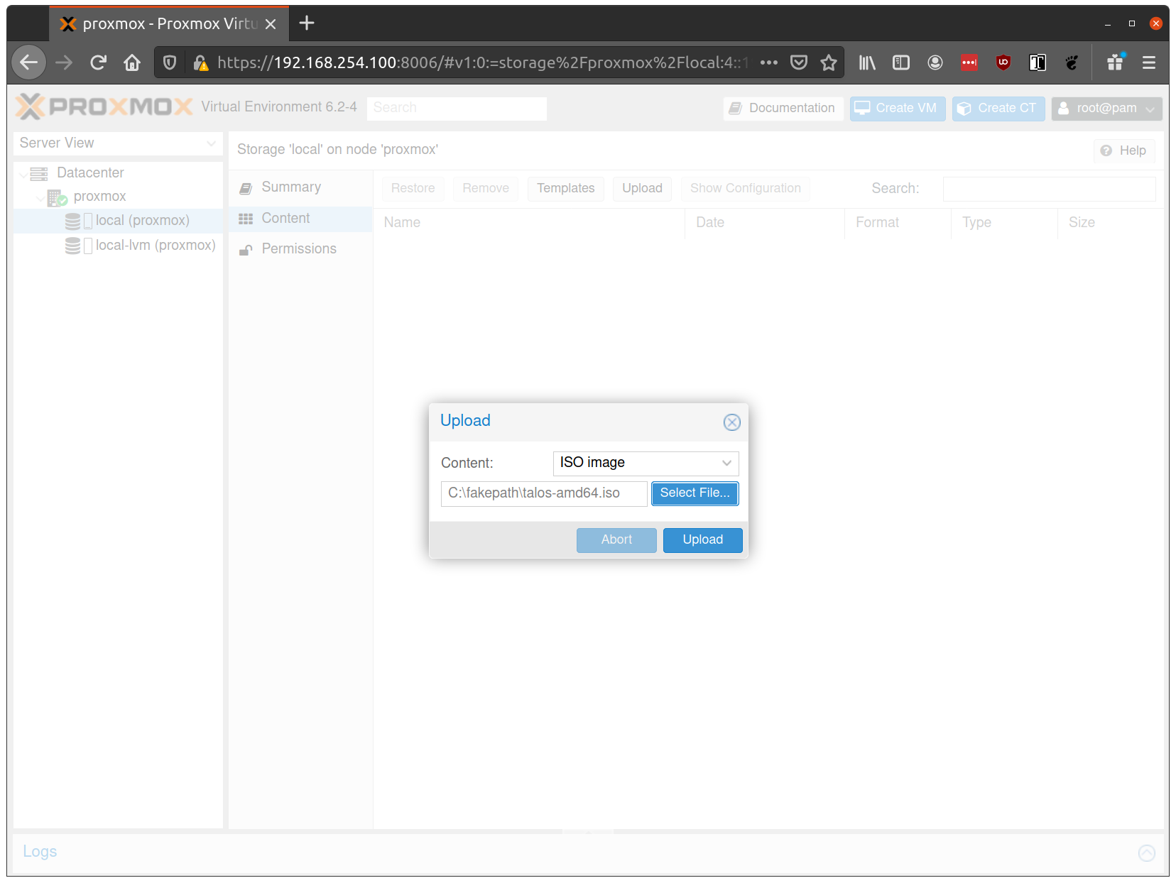
From the Proxmox UI, select the “local” storage and enter the “Content” section. Click the “Upload” button:
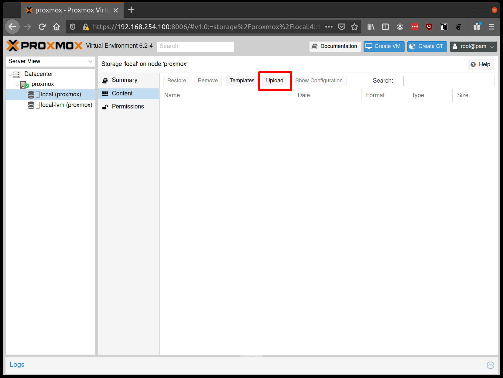
Select the ISO you downloaded previously, then hit “Upload”
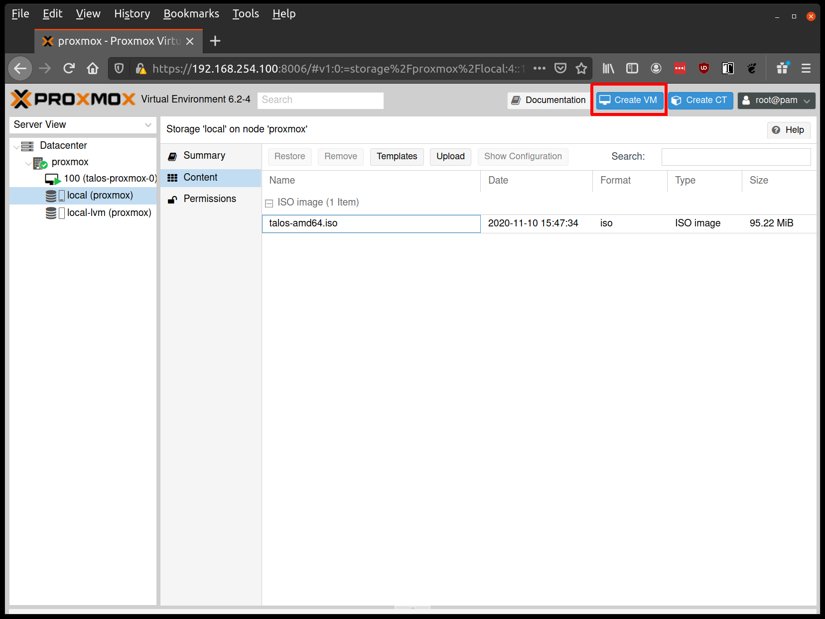
Create VMs
Before starting, familiarise yourself with the system requirements for Talos and assign VM resources accordingly.
Create a new VM by clicking the “Create VM” button in the Proxmox UI:
Fill out a name for the new VM:
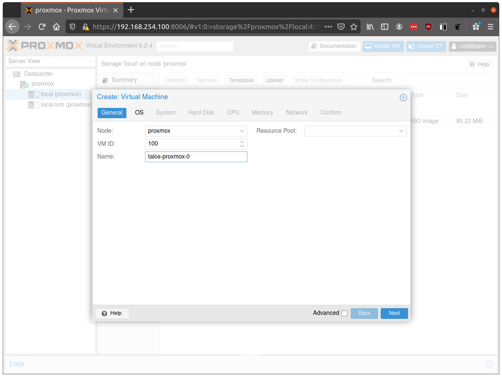
In the OS tab, select the ISO we uploaded earlier:
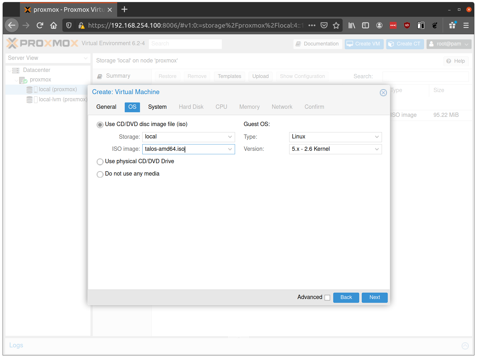
Keep the defaults set in the “System” tab.
Keep the defaults in the “Hard Disk” tab as well, only changing the size if desired.
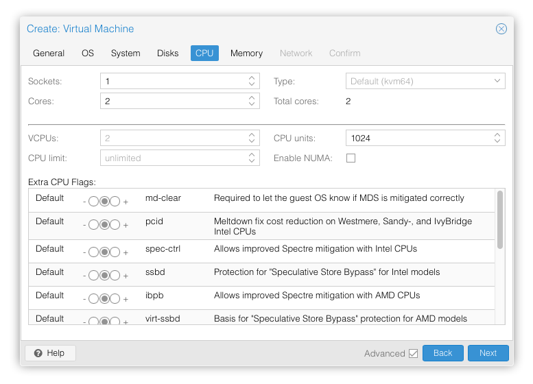
In the “CPU” section, give at least 2 cores to the VM:
Note: As of Talos v1.0 (which requires the x86-64-v2 microarchitecture), prior to Proxmox V8.0, booting with the default Processor Type
kvm64will not work. You can enable the required CPU features after creating the VM by adding the following line in the corresponding/etc/pve/qemu-server/<vmid>.conffile:args: -cpu kvm64,+cx16,+lahf_lm,+popcnt,+sse3,+ssse3,+sse4.1,+sse4.2Alternatively, you can set the Processor Type to
hostif your Proxmox host supports these CPU features, this however prevents using live VM migration.
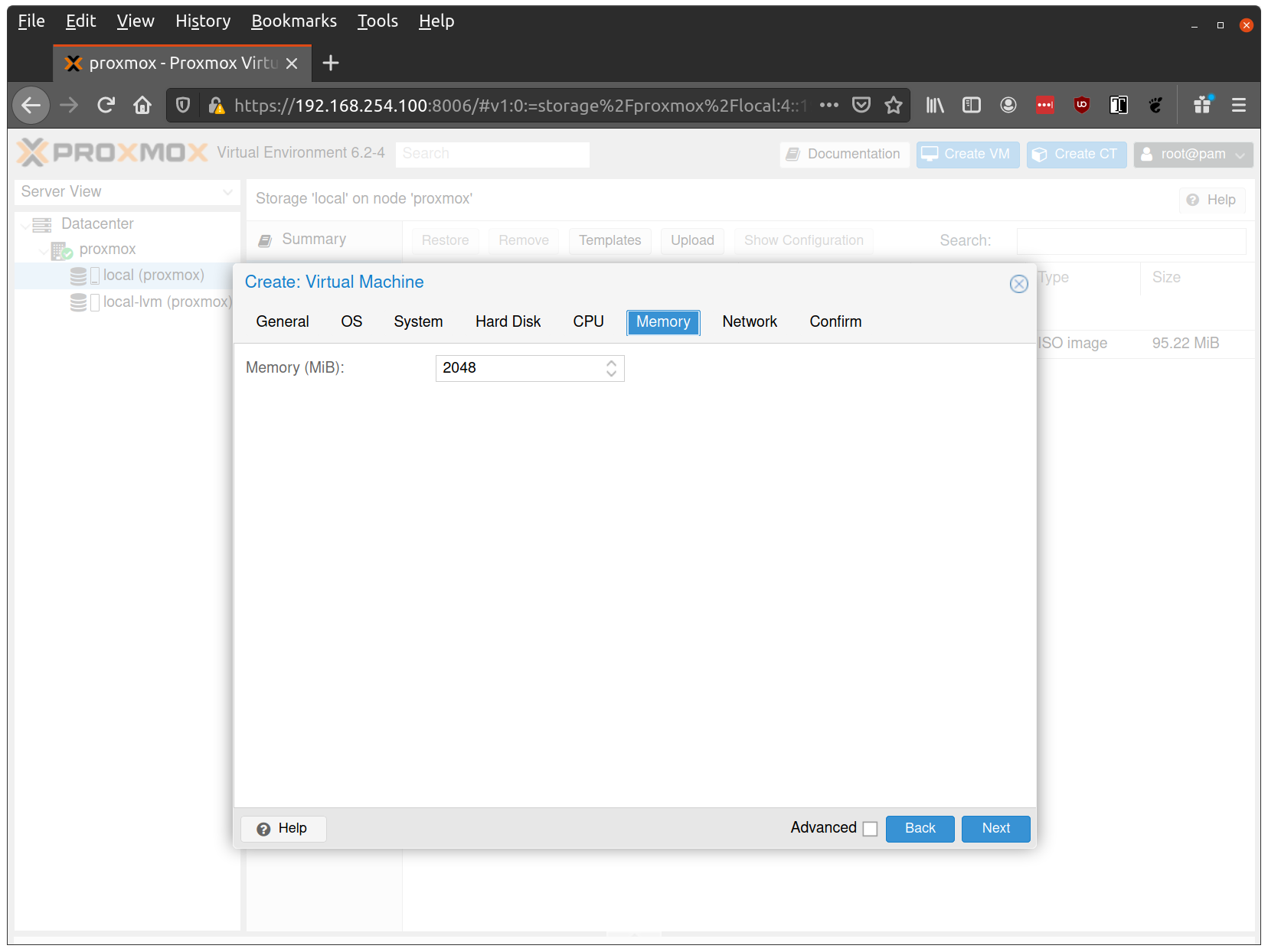
Verify that the RAM is set to at least 2GB:
Keep the default values for networking, verifying that the VM is set to come up on the bridge interface:
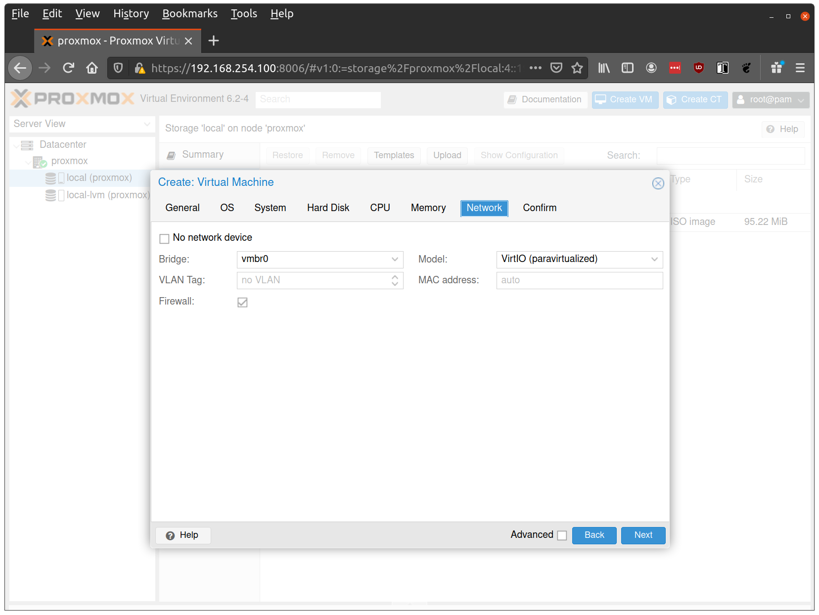
Finish creating the VM by clicking through the “Confirm” tab and then “Finish”.
Repeat this process for a second VM to use as a worker node. You can also repeat this for additional nodes desired.
Note: Talos doesn’t support memory hot plugging, if creating the VM programmatically don’t enable memory hotplug on your Talos VM’s. Doing so will cause Talos to be unable to see all available memory and have insufficient memory to complete installation of the cluster.
Start Control Plane Node
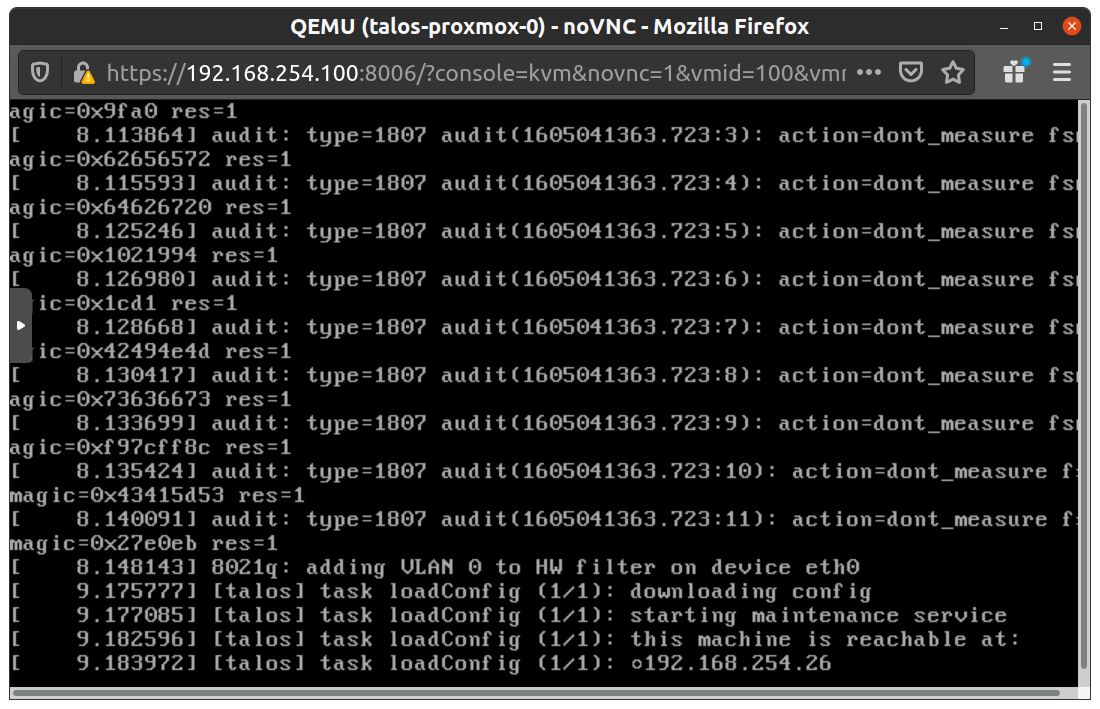
Once the VMs have been created and updated, start the VM that will be the first control plane node. This VM will boot the ISO image specified earlier and enter “maintenance mode”.
With DHCP server
Once the machine has entered maintenance mode, there will be a console log that details the IP address that the node received.
Take note of this IP address, which will be referred to as $CONTROL_PLANE_IP for the rest of this guide.
If you wish to export this IP as a bash variable, simply issue a command like export CONTROL_PLANE_IP=1.2.3.4.
Without DHCP server
To apply the machine configurations in maintenance mode, VM has to have IP on the network. So you can set it on boot time manually.
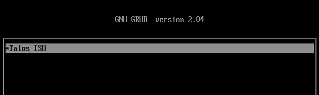
Press e on the boot time.
And set the IP parameters for the VM.
Format is:
ip=<client-ip>:<srv-ip>:<gw-ip>:<netmask>:<host>:<device>:<autoconf>
For example $CONTROL_PLANE_IP will be 192.168.0.100 and gateway 192.168.0.1
linux /boot/vmlinuz init_on_alloc=1 slab_nomerge pti=on panic=0 consoleblank=0 printk.devkmsg=on earlyprintk=ttyS0 console=tty0 console=ttyS0 talos.platform=metal ip=192.168.0.100::192.168.0.1:255.255.255.0::eth0:off
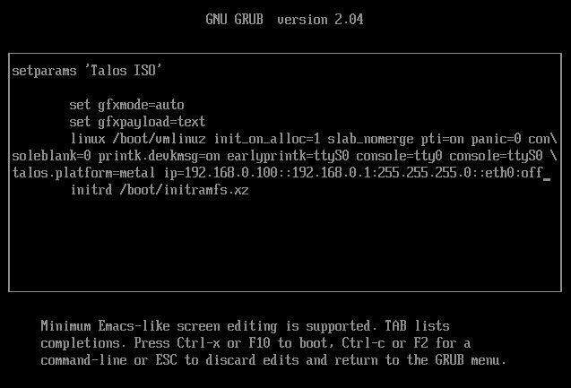
Then press Ctrl-x or F10
Generate Machine Configurations
With the IP address above, you can now generate the machine configurations to use for installing Talos and Kubernetes. Issue the following command, updating the output directory, cluster name, and control plane IP as you see fit:
talosctl gen config talos-proxmox-cluster https://$CONTROL_PLANE_IP:6443 --output-dir _out
This will create several files in the _out directory: controlplane.yaml, worker.yaml, and talosconfig.
Note: The Talos config by default will install to
/dev/sda. Depending on your setup the virtual disk may be mounted differently Eg:/dev/vda. You can check for disks running the following command:talosctl disks --insecure --nodes $CONTROL_PLANE_IPUpdate
controlplane.yamlandworker.yamlconfig files to point to the correct disk location.
QEMU guest agent support
For QEMU guest agent support, you can generate the config with the custom install image:
talosctl gen config talos-proxmox-cluster https://$CONTROL_PLANE_IP:6443 --output-dir _out --install-image factory.talos.dev/installer/ce4c980550dd2ab1b17bbf2b08801c7eb59418eafe8f279833297925d67c7515:v1.7.6
- In Proxmox, go to your VM –> Options and ensure that
QEMU Guest AgentisEnabled - The QEMU agent is now configured
Create Control Plane Node
Using the controlplane.yaml generated above, you can now apply this config using talosctl.
Issue:
talosctl apply-config --insecure --nodes $CONTROL_PLANE_IP --file _out/controlplane.yaml
You should now see some action in the Proxmox console for this VM. Talos will be installed to disk, the VM will reboot, and then Talos will configure the Kubernetes control plane on this VM.
Note: This process can be repeated multiple times to create an HA control plane.
Create Worker Node
Create at least a single worker node using a process similar to the control plane creation above.
Start the worker node VM and wait for it to enter “maintenance mode”.
Take note of the worker node’s IP address, which will be referred to as $WORKER_IP
Issue:
talosctl apply-config --insecure --nodes $WORKER_IP --file _out/worker.yaml
Note: This process can be repeated multiple times to add additional workers.
Using the Cluster
Once the cluster is available, you can make use of talosctl and kubectl to interact with the cluster.
For example, to view current running containers, run talosctl containers for a list of containers in the system namespace, or talosctl containers -k for the k8s.io namespace.
To view the logs of a container, use talosctl logs <container> or talosctl logs -k <container>.
First, configure talosctl to talk to your control plane node by issuing the following, updating paths and IPs as necessary:
export TALOSCONFIG="_out/talosconfig"
talosctl config endpoint $CONTROL_PLANE_IP
talosctl config node $CONTROL_PLANE_IP
Bootstrap Etcd
talosctl bootstrap
Retrieve the kubeconfig
At this point we can retrieve the admin kubeconfig by running:
talosctl kubeconfig .
Cleaning Up
To cleanup, simply stop and delete the virtual machines from the Proxmox UI.
1.2.5 - Vagrant & Libvirt
Pre-requisities
- Linux OS
- Vagrant installed
- vagrant-libvirt plugin installed
- talosctl installed
- kubectl installed
Overview
We will use Vagrant and its libvirt plugin to create a KVM-based cluster with 3 control plane nodes and 1 worker node.
For this, we will mount Talos ISO into the VMs using a virtual CD-ROM, and configure the VMs to attempt to boot from the disk first with the fallback to the CD-ROM.
We will also configure a virtual IP address on Talos to achieve high-availability on kube-apiserver.
Preparing the environment
First, we download the latest metal-amd64.iso ISO from GitHub releases into the /tmp directory.
wget --timestamping https://github.com/siderolabs/talos/releases/download/v1.7.6/metal-amd64.iso -O /tmp/metal-amd64.iso
Create a Vagrantfile with the following contents:
Vagrant.configure("2") do |config|
  config.vm.define "control-plane-node-1" do |vm|
    vm.vm.provider :libvirt do |domain|
      domain.cpus = 2
      domain.memory = 2048
      domain.serial :type => "file", :source => {:path => "/tmp/control-plane-node-1.log"}
      domain.storage :file, :device => :cdrom, :path => "/tmp/metal-amd64.iso"
      domain.storage :file, :size => '4G', :type => 'raw'
      domain.boot 'hd'
      domain.boot 'cdrom'
    end
  end

  config.vm.define "control-plane-node-2" do |vm|
    vm.vm.provider :libvirt do |domain|
      domain.cpus = 2
      domain.memory = 2048
      domain.serial :type => "file", :source => {:path => "/tmp/control-plane-node-2.log"}
      domain.storage :file, :device => :cdrom, :path => "/tmp/metal-amd64.iso"
      domain.storage :file, :size => '4G', :type => 'raw'
      domain.boot 'hd'
      domain.boot 'cdrom'
    end
  end

  config.vm.define "control-plane-node-3" do |vm|
    vm.vm.provider :libvirt do |domain|
      domain.cpus = 2
      domain.memory = 2048
      domain.serial :type => "file", :source => {:path => "/tmp/control-plane-node-3.log"}
      domain.storage :file, :device => :cdrom, :path => "/tmp/metal-amd64.iso"
      domain.storage :file, :size => '4G', :type => 'raw'
      domain.boot 'hd'
      domain.boot 'cdrom'
    end
  end

  config.vm.define "worker-node-1" do |vm|
    vm.vm.provider :libvirt do |domain|
      domain.cpus = 1
      domain.memory = 1024
      domain.serial :type => "file", :source => {:path => "/tmp/worker-node-1.log"}
      domain.storage :file, :device => :cdrom, :path => "/tmp/metal-amd64.iso"
      domain.storage :file, :size => '4G', :type => 'raw'
      domain.boot 'hd'
      domain.boot 'cdrom'
    end
  end
end
Bring up the nodes
Check the status of vagrant VMs:
vagrant status
You should see the VMs in “not created” state:
Current machine states:

control-plane-node-1      not created (libvirt)
control-plane-node-2      not created (libvirt)
control-plane-node-3      not created (libvirt)
worker-node-1             not created (libvirt)
Bring up the vagrant environment:
vagrant up --provider=libvirt
Check the status again:
vagrant status
Now you should see the VMs in “running” state:
Current machine states:

control-plane-node-1      running (libvirt)
control-plane-node-2      running (libvirt)
control-plane-node-3      running (libvirt)
worker-node-1             running (libvirt)
Find out the IP addresses assigned by the libvirt DHCP by running:
virsh list | grep vagrant | awk '{print $2}' | xargs -t -L1 virsh domifaddr
Output will look like the following:
virsh domifaddr vagrant_control-plane-node-2
 Name       MAC address          Protocol     Address
-------------------------------------------------------------------------------
 vnet0      52:54:00:f9:10:e5    ipv4         192.168.121.119/24

virsh domifaddr vagrant_control-plane-node-1
 Name       MAC address          Protocol     Address
-------------------------------------------------------------------------------
 vnet1      52:54:00:0f:ae:59    ipv4         192.168.121.203/24

virsh domifaddr vagrant_worker-node-1
 Name       MAC address          Protocol     Address
-------------------------------------------------------------------------------
 vnet2      52:54:00:6f:28:95    ipv4         192.168.121.69/24

virsh domifaddr vagrant_control-plane-node-3
 Name       MAC address          Protocol     Address
-------------------------------------------------------------------------------
 vnet3      52:54:00:03:45:10    ipv4         192.168.121.125/24
Our control plane nodes have the IPs: 192.168.121.203, 192.168.121.119, 192.168.121.125 and the worker node has the IP 192.168.121.69.
Now you should be able to interact with Talos nodes that are in maintenance mode:
talosctl -n 192.168.121.203 disks --insecure
Sample output:
DEV        MODEL   SERIAL   TYPE   UUID   WWID   MODALIAS                    NAME   SIZE     BUS_PATH
/dev/vda   -       -        HDD    -      -      virtio:d00000002v00001AF4   -      8.6 GB   /pci0000:00/0000:00:03.0/virtio0/
Installing Talos
Pick an endpoint IP in the vagrant-libvirt subnet but not used by any nodes, for example 192.168.121.100.
Generate a machine configuration:
talosctl gen config my-cluster https://192.168.121.100:6443 --install-disk /dev/vda
Edit controlplane.yaml to add the virtual IP you picked to a network interface under .machine.network.interfaces, for example:
machine:
  network:
    interfaces:
      - interface: eth0
        dhcp: true
        vip:
          ip: 192.168.121.100
Apply the configuration to the initial control plane node:
talosctl -n 192.168.121.203 apply-config --insecure --file controlplane.yaml
You can tail the logs of the node:
sudo tail -f /tmp/control-plane-node-1.log
Set up your shell to use the generated talosconfig and configure its endpoints (use the IPs of the control plane nodes):
export TALOSCONFIG=$(realpath ./talosconfig)
talosctl config endpoint 192.168.121.203 192.168.121.119 192.168.121.125
Bootstrap the Kubernetes cluster from the initial control plane node:
talosctl -n 192.168.121.203 bootstrap
Finally, apply the machine configurations to the remaining nodes:
talosctl -n 192.168.121.119 apply-config --insecure --file controlplane.yaml
talosctl -n 192.168.121.125 apply-config --insecure --file controlplane.yaml
talosctl -n 192.168.121.69 apply-config --insecure --file worker.yaml
After a while, you should see that all the members have joined:
talosctl -n 192.168.121.203 get members
The output will be like the following:
NODE              NAMESPACE   TYPE     ID                      VERSION   HOSTNAME                MACHINE TYPE   OS               ADDRESSES
192.168.121.203   cluster     Member   talos-192-168-121-119   1         talos-192-168-121-119   controlplane   Talos (v1.1.0)   ["192.168.121.119"]
192.168.121.203   cluster     Member   talos-192-168-121-69    1         talos-192-168-121-69    worker         Talos (v1.1.0)   ["192.168.121.69"]
192.168.121.203   cluster     Member   talos-192-168-121-203   6         talos-192-168-121-203   controlplane   Talos (v1.1.0)   ["192.168.121.100","192.168.121.203"]
192.168.121.203   cluster     Member   talos-192-168-121-125   1         talos-192-168-121-125   controlplane   Talos (v1.1.0)   ["192.168.121.125"]
Interacting with Kubernetes cluster
Retrieve the kubeconfig from the cluster:
talosctl -n 192.168.121.203 kubeconfig ./kubeconfig
List the nodes in the cluster:
kubectl --kubeconfig ./kubeconfig get node -owide
You will see an output similar to:
NAME                    STATUS   ROLES                  AGE     VERSION   INTERNAL-IP       EXTERNAL-IP   OS-IMAGE         KERNEL-VERSION   CONTAINER-RUNTIME
talos-192-168-121-203   Ready    control-plane,master   3m10s   v1.24.2   192.168.121.203   <none>        Talos (v1.1.0)   5.15.48-talos    containerd://1.6.6
talos-192-168-121-69    Ready    <none>                 2m25s   v1.24.2   192.168.121.69    <none>        Talos (v1.1.0)   5.15.48-talos    containerd://1.6.6
talos-192-168-121-119   Ready    control-plane,master   8m46s   v1.24.2   192.168.121.119   <none>        Talos (v1.1.0)   5.15.48-talos    containerd://1.6.6
talos-192-168-121-125   Ready    control-plane,master   3m11s   v1.24.2   192.168.121.125   <none>        Talos (v1.1.0)   5.15.48-talos    containerd://1.6.6
Congratulations, you have a highly-available Talos cluster running!
Cleanup
You can destroy the vagrant environment by running:
vagrant destroy -f
And remove the ISO image you downloaded:
sudo rm -f /tmp/metal-amd64.iso
1.2.6 - VMware
Creating a Cluster via the govc CLI
In this guide we will create an HA Kubernetes cluster with 2 worker nodes.
We will use the govc cli which can be downloaded here.
Prereqs/Assumptions
This guide will use the virtual IP (“VIP”) functionality that is built into Talos in order to provide a stable, known IP for the Kubernetes control plane. This simply means the user should pick an IP on their “VM Network” to designate for this purpose and keep it handy for future steps.
Create the Machine Configuration Files
Generating Base Configurations
Using the VIP chosen in the prereq steps, we will now generate the base configuration files for the Talos machines.
This can be done with the talosctl gen config ... command.
Take note that we will also use a JSON6902 patch when creating the configs so that the control plane nodes get some special information about the VIP we chose earlier, as well as a daemonset to install vmware tools on talos nodes.
First, download cp.patch.yaml to your local machine and edit the VIP to match your chosen IP.
You can do this by issuing: curl -fsSLO https://raw.githubusercontent.com/siderolabs/talos/master/website/content/v1.7/talos-guides/install/virtualized-platforms/vmware/cp.patch.yaml.
It’s contents should look like the following:
- op: add
  path: /machine/network
  value:
    interfaces:
    - interface: eth0
      dhcp: true
      vip:
        ip: <VIP>
With the patch in hand, generate machine configs with:
$ talosctl gen config vmware-test https://<VIP>:<port> --config-patch-control-plane @cp.patch.yaml
created controlplane.yaml
created worker.yaml
created talosconfig
At this point, you can modify the generated configs to your liking if needed.
Optionally, you can specify additional patches by adding to the cp.patch.yaml file downloaded earlier, or create your own patch files.
Validate the Configuration Files
$ talosctl validate --config controlplane.yaml --mode cloud
controlplane.yaml is valid for cloud mode
$ talosctl validate --config worker.yaml --mode cloud
worker.yaml is valid for cloud mode
Set Environment Variables
govc makes use of the following environment variables
export GOVC_URL=<vCenter url>
export GOVC_USERNAME=<vCenter username>
export GOVC_PASSWORD=<vCenter password>
Note: If your vCenter installation makes use of self signed certificates, you’ll want to export
GOVC_INSECURE=true.
There are some additional variables that you may need to set:
export GOVC_DATACENTER=<vCenter datacenter>
export GOVC_RESOURCE_POOL=<vCenter resource pool>
export GOVC_DATASTORE=<vCenter datastore>
export GOVC_NETWORK=<vCenter network>
Choose Install Approach
As part of this guide, we have a more automated install script that handles some of the complexity of importing OVAs and creating VMs. If you wish to use this script, we will detail that next. If you wish to carry out the manual approach, simply skip ahead to the “Manual Approach” section.
Scripted Install
Download the vmware.sh script to your local machine.
You can do this by issuing curl -fsSL "https://raw.githubusercontent.com/siderolabs/talos/master/website/content/v1.7/talos-guides/install/virtualized-platforms/vmware/vmware.sh" | sed s/latest/v1.7.6/ > vmware.sh.
This script has default variables for things like Talos version and cluster name that may be interesting to tweak before deploying.
The script downloads VMWare OVA with talos-vmtoolsd from Image Factory extension pre-installed.
Import OVA
To create a content library and import the Talos OVA corresponding to the mentioned Talos version, simply issue:
./vmware.sh upload_ova
Create Cluster
With the OVA uploaded to the content library, you can create a 5 node (by default) cluster with 3 control plane and 2 worker nodes:
./vmware.sh create
This step will create a VM from the OVA, edit the settings based on the env variables used for VM size/specs, then power on the VMs.
You may now skip past the “Manual Approach” section down to “Bootstrap Cluster”.
Manual Approach
Import the OVA into vCenter
A talos.ova asset is published with each release.
We will refer to the version of the release as $TALOS_VERSION below.
It can be easily exported with export TALOS_VERSION="v0.3.0-alpha.10" or similar.
curl -LO https://github.com/siderolabs/talos/releases/download/$TALOS_VERSION/talos.ova
Create a content library (if needed) with:
govc library.create <library name>
Import the OVA to the library with:
govc library.import -n talos-${TALOS_VERSION} <library name> /path/to/downloaded/talos.ova
Create the Bootstrap Node
We’ll clone the OVA to create the bootstrap node (our first control plane node).
govc library.deploy <library name>/talos-${TALOS_VERSION} control-plane-1
Talos makes use of the guestinfo facility of VMware to provide the machine/cluster configuration.
This can be set using the govc vm.change command.
To facilitate persistent storage using the vSphere cloud provider integration with Kubernetes, disk.enableUUID=1 is used.
govc vm.change \
  -e "guestinfo.talos.config=$(cat controlplane.yaml | base64)" \
  -e "disk.enableUUID=1" \
  -vm control-plane-1
Update Hardware Resources for the Bootstrap Node
-cis used to configure the number of cpus-mis used to configure the amount of memory (in MB)
govc vm.change \
  -c 2 \
  -m 4096 \
  -vm control-plane-1
The following can be used to adjust the EPHEMERAL disk size.
govc vm.disk.change -vm control-plane-1 -disk.name disk-1000-0 -size 10G
govc vm.power -on control-plane-1
Create the Remaining Control Plane Nodes
govc library.deploy <library name>/talos-${TALOS_VERSION} control-plane-2
govc vm.change \
  -e "guestinfo.talos.config=$(base64 controlplane.yaml)" \
  -e "disk.enableUUID=1" \
  -vm control-plane-2

govc library.deploy <library name>/talos-${TALOS_VERSION} control-plane-3
govc vm.change \
  -e "guestinfo.talos.config=$(base64 controlplane.yaml)" \
  -e "disk.enableUUID=1" \
  -vm control-plane-3
govc vm.change \
  -c 2 \
  -m 4096 \
  -vm control-plane-2

govc vm.change \
  -c 2 \
  -m 4096 \
  -vm control-plane-3
govc vm.disk.change -vm control-plane-2 -disk.name disk-1000-0 -size 10G

govc vm.disk.change -vm control-plane-3 -disk.name disk-1000-0 -size 10G
govc vm.power -on control-plane-2

govc vm.power -on control-plane-3
Update Settings for the Worker Nodes
govc library.deploy <library name>/talos-${TALOS_VERSION} worker-1
govc vm.change \
  -e "guestinfo.talos.config=$(base64 worker.yaml)" \
  -e "disk.enableUUID=1" \
  -vm worker-1

govc library.deploy <library name>/talos-${TALOS_VERSION} worker-2
govc vm.change \
  -e "guestinfo.talos.config=$(base64 worker.yaml)" \
  -e "disk.enableUUID=1" \
  -vm worker-2
govc vm.change \
  -c 4 \
  -m 8192 \
  -vm worker-1

govc vm.change \
  -c 4 \
  -m 8192 \
  -vm worker-2
govc vm.disk.change -vm worker-1 -disk.name disk-1000-0 -size 10G

govc vm.disk.change -vm worker-2 -disk.name disk-1000-0 -size 10G
govc vm.power -on worker-1

govc vm.power -on worker-2
Bootstrap Cluster
In the vSphere UI, open a console to one of the control plane nodes. You should see some output stating that etcd should be bootstrapped. This text should look like:
"etcd is waiting to join the cluster, if this node is the first node in the cluster, please run `talosctl bootstrap` against one of the following IPs:
Take note of the IP mentioned here and issue:
talosctl --talosconfig talosconfig bootstrap -e <control plane IP> -n <control plane IP>
Keep this IP handy for the following steps as well.
Retrieve the kubeconfig
At this point we can retrieve the admin kubeconfig by running:
talosctl --talosconfig talosconfig config endpoint <control plane IP>
talosctl --talosconfig talosconfig config node <control plane IP>
talosctl --talosconfig talosconfig kubeconfig .
Configure talos-vmtoolsd
The talos-vmtoolsd application was deployed as a daemonset as part of the cluster creation; however, we must now provide a talos credentials file for it to use.
Create a new talosconfig with:
talosctl --talosconfig talosconfig -n <control plane IP> config new vmtoolsd-secret.yaml --roles os:admin
Create a secret from the talosconfig:
kubectl -n kube-system create secret generic talos-vmtoolsd-config \
  --from-file=talosconfig=./vmtoolsd-secret.yaml
Clean up the generated file from local system:
rm vmtoolsd-secret.yaml
Once configured, you should now see these daemonset pods go into “Running” state and in vCenter, you will now see IPs and info from the Talos nodes present in the UI.
1.2.7 - Xen
Talos is known to work on Xen. We don’t yet have a documented guide specific to Xen; however, you can follow the General Getting Started Guide. If you run into any issues, our community can probably help!
1.3 - Cloud Platforms
1.3.1 - Akamai
Creating a Talos Linux Cluster on Akamai Connected Cloud via the CLI
This guide will demonstrate how to create a highly available Kubernetes cluster with one worker using the Akamai Connected Cloud provider.
Akamai Connected Cloud has a very well-documented REST API, and an open-source CLI tool to interact with the API which will be used in this guide.
Make sure to follow installation and authentication instructions for the linode-cli tool.
jq and talosctl also needs to be installed
Upload image
Download the Akamai image akamai-amd64.raw.gz from the latest Talos release.
Upload the image
export REGION=us-ord

linode-cli image-upload --region ${REGION} --label talos akamai-amd64.raw.gz
Create a Load Balancer
export REGION=us-ord

linode-cli nodebalancers create --region ${REGION} --no-defaults --label talos
export NODEBALANCER_ID=$(linode-cli nodebalancers list --label talos --format id --text --no-headers)
linode-cli nodebalancers config-create --port 443 --protocol tcp --check connection ${NODEBALANCER_ID}
Create the Machine Configuration Files
Using the IP address (or DNS name, if you have created one) of the load balancer, generate the base configuration files for the Talos machines. Also note that the load balancer forwards port 443 to port 6443 on the associated nodes, so we should use 443 as the port in the config definition:
export NODEBALANCER_IP=$(linode-cli nodebalancers list --label talos --format ipv4 --text --no-headers)

talosctl gen config talos-kubernetes-akamai https://${NODEBALANCER_IP} --with-examples=false
Create the Linodes
Create the Control Plane Nodes
Although root passwords are not used by Talos, Linode requires that a root password be associated with a linode during creation.
Run the following commands to create three control plane nodes:
export IMAGE_ID=$(linode-cli images list --label talos --format id --text --no-headers)
export NODEBALANCER_ID=$(linode-cli nodebalancers list --label talos --format id --text --no-headers)
export NODEBALANCER_CONFIG_ID=$(linode-cli nodebalancers configs-list ${NODEBALANCER_ID} --format id --text --no-headers)
export REGION=us-ord
export LINODE_TYPE=g6-standard-4
export ROOT_PW=$(pwgen 16)

for id in $(seq 3); do
  linode_label="talos-control-plane-${id}"

  # create linode

  linode-cli linodes create  \
    --no-defaults \
    --root_pass ${ROOT_PW} \
    --type ${LINODE_TYPE} \
    --region ${REGION} \
    --image ${IMAGE_ID} \
    --label ${linode_label} \
    --private_ip true \
    --tags talos-control-plane \
    --group "talos-control-plane" \
    --metadata.user_data "$(base64 -i ./controlplane.yaml)"

  # change kernel to "direct disk"
  linode_id=$(linode-cli linodes list --label ${linode_label} --format id --text --no-headers)
  confiig_id=$(linode-cli linodes configs-list ${linode_id} --format id --text --no-headers)
  linode-cli linodes config-update ${linode_id} ${confiig_id} --kernel "linode/direct-disk"

  # add machine to nodebalancer
  private_ip=$(linode-cli linodes list --label ${linode_label} --format ipv4 --json | jq -r ".[0].ipv4[1]")
  linode-cli nodebalancers node-create ${NODEBALANCER_ID}  ${NODEBALANCER_CONFIG_ID}  --label ${linode_label} --address ${private_ip}:6443
done
Create the Worker Nodes
Although root passwords are not used by Talos, Linode requires that a root password be associated with a linode during creation.
Run the following to create a worker node:
export IMAGE_ID=$(linode-cli images list --label talos --format id --text --no-headers)
export REGION=us-ord
export LINODE_TYPE=g6-standard-4
export LINODE_LABEL="talos-worker-1"
export ROOT_PW=$(pwgen 16)

linode-cli linodes create  \
    --no-defaults \
    --root_pass ${ROOT_PW} \
    --type ${LINODE_TYPE} \
    --region ${REGION} \
    --image ${IMAGE_ID} \
    --label ${LINODE_LABEL} \
    --private_ip true \
    --tags talos-worker \
    --group "talos-worker" \
    --metadata.user_data "$(base64 -i ./worker.yaml)"

linode_id=$(linode-cli linodes list --label ${LINODE_LABEL} --format id --text --no-headers)
config_id=$(linode-cli linodes configs-list ${linode_id} --format id --text --no-headers)
linode-cli linodes config-update ${linode_id} ${config_id} --kernel "linode/direct-disk"
Bootstrap Etcd
Set the endpoints and nodes:
export LINODE_LABEL=talos-control-plane-1
export LINODE_IP=$(linode-cli linodes list --label ${LINODE_LABEL} --format ipv4 --json | jq -r ".[0].ipv4[0]")
talosctl --talosconfig talosconfig config endpoint ${LINODE_IP}
talosctl --talosconfig talosconfig config node ${LINODE_IP}
Bootstrap etcd:
talosctl --talosconfig talosconfig bootstrap
Retrieve the kubeconfig
At this point, we can retrieve the admin kubeconfig by running:
talosctl --talosconfig talosconfig kubeconfig .
We can also watch the cluster bootstrap via:
talosctl --talosconfig talosconfig health
Alternatively, we can also watch the node overview, logs and real-time metrics dashboard via:
talosctl --talosconfig talosconfig dashboard
1.3.2 - AWS
Creating a Cluster via the AWS CLI
In this guide we will create an HA Kubernetes cluster with 3 control plane nodes across 3 availability zones. You should have an existing AWS account and have the AWS CLI installed and configured. If you need more information on AWS specifics, please see the official AWS documentation.
To install the dependencies for this tutorial you can use homebrew on macOS or Linux:
brew install siderolabs/tap/talosctl kubectl jq curl xz
If you would like to create infrastructure via terraform or opentofu please see the example in the contrib repository.
Note: this guide is not a production set up and steps were tested in
bashandzshshells.
Create AWS Resources
We will be creating a control plane with 3 Ec2 instances spread across 3 availability zones. It is recommended to not use the default VPC so we will create a new one for this tutorial.
Change to your desired region and CIDR block and create a VPC:
Make sure your subnet does not overlap with
10.244.0.0/16or10.96.0.0/12the default pod and services subnets in Kubernetes.
AWS_REGION="us-west-2"
IPV4_CIDR="10.1.0.0/18"
VPC_ID=$(aws ec2 create-vpc \
    --cidr-block $IPV4_CIDR \
    --output text --query 'Vpc.VpcId')
Create the Subnets
Create 3 smaller CIDRs to use for each subnet in different availability zones. Make sure to adjust these CIDRs if you changed the default value from the last command.
IPV4_CIDRS=( "10.1.0.0/22" "10.1.4.0/22" "10.1.8.0/22" )
Next create a subnet in each availability zones.
Note: If you’re using zsh you need to run
setopt KSH_ARRAYSto have arrays referenced properly.
CIDR=0
declare -a SUBNETS
AZS=($(aws ec2 describe-availability-zones \
    --query 'AvailabilityZones[].ZoneName' \
    --filter "Name=state,Values=available" \
    --output text | tr -s '\t' '\n' | head -n3))

for AZ in ${AZS[@]}; do
        SUBNETS[$CIDR]=$(aws ec2 create-subnet \
            --vpc-id $VPC_ID \
            --availability-zone $AZ \
            --cidr-block ${IPV4_CIDRS[$CIDR]} \
            --query 'Subnet.SubnetId' \
            --output text)
        aws ec2 modify-subnet-attribute \
            --subnet-id ${SUBNETS[$CIDR]} \
            --private-dns-hostname-type-on-launch resource-name
        echo ${SUBNETS[$CIDR]}
        ((CIDR++))
done
Create an internet gateway and attach it to the VPC:
IGW_ID=$(aws ec2 create-internet-gateway \
    --query 'InternetGateway.InternetGatewayId' \
    --output text)

aws ec2 attach-internet-gateway \
    --vpc-id $VPC_ID \
    --internet-gateway-id $IGW_ID

ROUTE_TABLE_ID=$(aws ec2 describe-route-tables \
        --filters "Name=vpc-id,Values=$VPC_ID" \
        --query 'RouteTables[].RouteTableId' \
        --output text)

aws ec2 create-route \
    --route-table-id $ROUTE_TABLE_ID \
    --destination-cidr-block 0.0.0.0/0 \
    --gateway-id $IGW_ID
Official AMI Images
Official AMI image ID can be found in the cloud-images.json file attached to the Talos release.
AMI=$(curl -sL https://github.com/siderolabs/talos/releases/download/v1.7.6/cloud-images.json | \
    jq -r '.[] | select(.region == "'$AWS_REGION'") | select (.arch == "amd64") | .id')
echo $AMI
If using the official AMIs, you can skip to Creating the Security group
Create your own AMIs
The use of the official Talos AMIs are recommended, but if you wish to build your own AMIs, follow the procedure below.
Create the S3 Bucket
aws s3api create-bucket \
    --bucket $BUCKET \
    --create-bucket-configuration LocationConstraint=$AWS_REGION \
    --acl private
Create the vmimport Role
In order to create an AMI, ensure that the vmimport role exists as described in the official AWS documentation.
Note that the role should be associated with the S3 bucket we created above.
Create the Image Snapshot
First, download the AWS image from a Talos release:
curl -L https://github.com/siderolabs/talos/releases/download/v1.7.6/aws-amd64.raw.xz | xz -d > disk.raw
Copy the RAW disk to S3 and import it as a snapshot:
aws s3 cp disk.raw s3://$BUCKET/talos-aws-tutorial.raw
$SNAPSHOT_ID=$(aws ec2 import-snapshot \
    --region $REGION \
    --description "Talos kubernetes tutorial" \
    --disk-container "Format=raw,UserBucket={S3Bucket=$BUCKET,S3Key=talos-aws-tutorial.raw}" \
    --query 'SnapshotId' \
    --output text)
To check on the status of the import, run:
aws ec2 describe-import-snapshot-tasks \
    --import-task-ids
Once the SnapshotTaskDetail.Status indicates completed, we can register the image.
Register the Image
AMI=$(aws ec2 register-image \
    --block-device-mappings "DeviceName=/dev/xvda,VirtualName=talos,Ebs={DeleteOnTermination=true,SnapshotId=$SNAPSHOT_ID,VolumeSize=4,VolumeType=gp2}" \
    --root-device-name /dev/xvda \
    --virtualization-type hvm \
    --architecture x86_64 \
    --ena-support \
    --name talos-aws-tutorial-ami \
    --query 'ImageId' \
    --output text)
We now have an AMI we can use to create our cluster.
Create a Security Group
SECURITY_GROUP_ID=$(aws ec2 create-security-group \
    --vpc-id $VPC_ID \
    --group-name talos-aws-tutorial-sg \
    --description "Security Group for EC2 instances to allow ports required by Talos" \
    --query 'GroupId' \
    --output text)
Using the security group from above, allow all internal traffic within the same security group:
aws ec2 authorize-security-group-ingress \
    --group-id $SECURITY_GROUP_ID \
    --protocol all \
    --port 0 \
    --source-group $SECURITY_GROUP_ID
Expose the Talos (50000) and Kubernetes API.
Note: This is only required for the control plane nodes. For a production environment you would want separate private subnets for worker nodes.
aws ec2 authorize-security-group-ingress \
    --group-id $SECURITY_GROUP_ID \
    --ip-permissions \
        IpProtocol=tcp,FromPort=50000,ToPort=50000,IpRanges="[{CidrIp=0.0.0.0/0}]" \
        IpProtocol=tcp,FromPort=6443,ToPort=6443,IpRanges="[{CidrIp=0.0.0.0/0}]" \
    --query 'SecurityGroupRules[].SecurityGroupRuleId' \
    --output text
We will bootstrap Talos with a MachineConfig via user-data it will never be exposed to the internet without certificate authentication.
We enable KubeSpan in this tutorial so you need to allow inbound UDP for the Wireguard port:
aws ec2 authorize-security-group-ingress \
    --group-id $SECURITY_GROUP_ID \
    --ip-permissions \
        IpProtocol=tcp,FromPort=51820,ToPort=51820,IpRanges="[{CidrIp=0.0.0.0/0}]" \
    --query 'SecurityGroupRules[].SecurityGroupRuleId' \
    --output text
Create a Load Balancer
The load balancer is used for a stable Kubernetes API endpoint.
LOAD_BALANCER_ARN=$(aws elbv2 create-load-balancer \
    --name talos-aws-tutorial-lb \
    --subnets $(echo ${SUBNETS[@]}) \
    --type network \
    --ip-address-type ipv4 \
    --query 'LoadBalancers[].LoadBalancerArn' \
    --output text)

LOAD_BALANCER_DNS=$(aws elbv2 describe-load-balancers \
    --load-balancer-arns $LOAD_BALANCER_ARN \
    --query 'LoadBalancers[].DNSName' \
    --output text)
Now create a target group for the load balancer:
TARGET_GROUP_ARN=$(aws elbv2 create-target-group \
    --name talos-aws-tutorial-tg \
    --protocol TCP \
    --port 6443 \
    --target-type instance \
    --vpc-id $VPC_ID \
    --query 'TargetGroups[].TargetGroupArn' \
    --output text)

LISTENER_ARN=$(aws elbv2 create-listener \
    --load-balancer-arn $LOAD_BALANCER_ARN \
    --protocol TCP \
    --port 6443 \
    --default-actions Type=forward,TargetGroupArn=$TARGET_GROUP_ARN \
    --query 'Listeners[].ListenerArn' \
    --output text)
Create the Machine Configuration Files
We will create a machine config patch to use the AWS time servers. You can create additional patches to customize the configuration as needed.
cat <<EOF > time-server-patch.yaml
machine:
  time:
    servers:
      - 169.254.169.123
EOF
Using the DNS name of the loadbalancer created earlier, generate the base configuration files for the Talos machines.
talosctl gen config talos-k8s-aws-tutorial https://${LOAD_BALANCER_DNS}:6443 \
    --with-examples=false \
    --with-docs=false \
    --with-kubespan \
    --install-disk /dev/xvda \
    --config-patch '@time-server-patch.yaml'
Note that the generated configs are too long for AWS userdata field if the
--with-examplesand--with-docsflags are not passed.
Create the EC2 Instances
Note: There is a known issue that prevents Talos from running on T2 instance types. Please use T3 if you need burstable instance types.
Create the Control Plane Nodes
declare -a CP_INSTANCES
INSTANCE_INDEX=0
for SUBNET in ${SUBNETS[@]}; do
    CP_INSTANCES[${INSTANCE_INDEX}]=$(aws ec2 run-instances \
        --image-id $AMI \
        --subnet-id $SUBNET \
        --instance-type t3.small \
        --user-data file://controlplane.yaml \
        --associate-public-ip-address \
        --security-group-ids $SECURITY_GROUP_ID \
        --count 1 \
        --tag-specifications "ResourceType=instance,Tags=[{Key=Name,Value=talos-aws-tutorial-cp-$INSTANCE_INDEX}]" \
        --query 'Instances[].InstanceId' \
        --output text)
    echo ${CP_INSTANCES[${INSTANCE_INDEX}]}
    ((INSTANCE_INDEX++))
done
Create the Worker Nodes
For the worker nodes we will create a new launch template with the worker.yaml machine configuration and create an autoscaling group.
WORKER_LAUNCH_TEMPLATE_ID=$(aws ec2 create-launch-template \
    --launch-template-name talos-aws-tutorial-worker \
    --launch-template-data '{
        "ImageId":"'$AMI'",
        "InstanceType":"t3.small",
        "UserData":"'$(base64 -w0 worker.yaml)'",
        "NetworkInterfaces":[{
            "DeviceIndex":0,
            "AssociatePublicIpAddress":true,
            "Groups":["'$SECURITY_GROUP_ID'"],
            "DeleteOnTermination":true
        }],
        "BlockDeviceMappings":[{
            "DeviceName":"/dev/xvda",
            "Ebs":{
                "VolumeSize":20,
                "VolumeType":"gp3",
                "DeleteOnTermination":true
            }
        }],
        "TagSpecifications":[{
            "ResourceType":"instance",
            "Tags":[{
          "Key":"Name",
          "Value":"talos-aws-tutorial-worker"
          }]
        }]}' \
    --query 'LaunchTemplate.LaunchTemplateId' \
    --output text)
aws autoscaling create-auto-scaling-group \
    --auto-scaling-group-name talos-aws-tutorial-worker \
    --min-size 1 \
    --max-size 3 \
    --desired-capacity 1 \
    --availability-zones $(echo ${AZS[@]}) \
    --target-group-arns $TARGET_GROUP_ARN \
    --launch-template "LaunchTemplateId=${WORKER_LAUNCH_TEMPLATE_ID}" \
    --vpc-zone-identifier $(echo ${SUBNETS[@]} | tr ' ' ',')
Configure the Load Balancer
Now, using the load balancer target group’s ARN, and the PrivateIpAddress from the controlplane instances that you created :
for INSTANCE in ${CP_INSTANCES[@]}; do
    aws elbv2 register-targets \
    --target-group-arn $TARGET_GROUP_ARN \
    --targets Id=$(aws ec2 describe-instances \
        --instance-ids $INSTANCE \
        --query 'Reservations[].Instances[].InstanceId' \
        --output text)
done
Bootstrap etcd
Export the talosconfig file so commands sent to Talos will be authenticated.
export TALOSCONFIG=$(pwd)/talosconfig

WORKER_INSTANCES=( $(aws autoscaling \
    describe-auto-scaling-instances \
    --query 'AutoScalingInstances[?AutoScalingGroupName==`talos-aws-tutorial-worker`].InstanceId' \
    --output text) )
Set the endpoints (the control plane node to which talosctl commands are sent) and nodes (the nodes that the command operates on):
talosctl config endpoints $(aws ec2 describe-instances \
    --instance-ids ${CP_INSTANCES[*]} \
    --query 'Reservations[].Instances[].PublicIpAddress' \
    --output text)

talosctl config nodes $(aws ec2 describe-instances \
    --instance-ids $(echo ${CP_INSTANCES[1]}) \
    --query 'Reservations[].Instances[].PublicIpAddress' \
    --output text)
Bootstrap etcd:
talosctl bootstrap
You can now watch as your cluster bootstraps, by using
talosctl health
This command will take a few minutes for the nodes to start etcd, reach quarom and start the Kubernetes control plane.
You can also watch the performance of a node, via:
talosctl dashboard
Retrieve the kubeconfig
When the cluster is healthy you can retrieve the admin kubeconfig by running:
talosctl kubeconfig .
export KUBECONFIG=$(pwd)/kubeconfig
And use standard kubectl commands.
kubectl get nodes
Cleanup resources
If you would like to delete all of the resources you created during this tutorial you can run the following commands.
aws elbv2 delete-listener --listener-arn $LISTENER_ARN
aws elbv2 delete-target-group --target-group-arn $TARGET_GROUP_ARN
aws elbv2 delete-load-balancer --load-balancer-arn $LOAD_BALANCER_ARN

aws autoscaling update-auto-scaling-group \
    --auto-scaling-group-name talos-aws-tutorial-worker \
    --min-size 0 \
    --max-size 0 \
    --desired-capacity 0

aws ec2 terminate-instances --instance-ids ${CP_INSTANCES[@]} ${WORKER_INSTANCES[@]} \
    --query 'TerminatingInstances[].InstanceId' \
    --output text

aws autoscaling delete-auto-scaling-group \
    --auto-scaling-group-name talos-aws-tutorial-worker \
    --force-delete

aws ec2 delete-launch-template --launch-template-id $WORKER_LAUNCH_TEMPLATE_ID

while $(aws ec2 describe-instances \
    --instance-ids ${CP_INSTANCES[@]} ${WORKER_INSTANCES[@]} \
    --query 'Reservations[].Instances[].[InstanceId,State.Name]' \
    --output text | grep -q shutting-down); do \
        echo "waiting for instances to terminate"; sleep 5s
done

aws ec2 detach-internet-gateway --vpc-id $VPC_ID --internet-gateway-id $IGW_ID
aws ec2 delete-internet-gateway --internet-gateway-id $IGW_ID

aws ec2 delete-security-group --group-id $SECURITY_GROUP_ID

for SUBNET in ${SUBNETS[@]}; do
    aws ec2 delete-subnet --subnet-id $SUBNET
done

aws ec2 delete-vpc --vpc-id $VPC_ID

rm -f controlplane.yaml worker.yaml talosconfig kubeconfig time-server-patch.yaml disk.raw
1.3.3 - Azure
Creating a Cluster via the CLI
In this guide we will create an HA Kubernetes cluster with 1 worker node. We assume existing Blob Storage, and some familiarity with Azure. If you need more information on Azure specifics, please see the official Azure documentation.
Environment Setup
We’ll make use of the following environment variables throughout the setup. Edit the variables below with your correct information.
# Storage account to use
export STORAGE_ACCOUNT="StorageAccountName"

# Storage container to upload to
export STORAGE_CONTAINER="StorageContainerName"

# Resource group name
export GROUP="ResourceGroupName"

# Location
export LOCATION="centralus"

# Get storage account connection string based on info above
export CONNECTION=$(az storage account show-connection-string \
                    -n $STORAGE_ACCOUNT \
                    -g $GROUP \
                    -o tsv)
Choose an Image
There are two methods of deployment in this tutorial.
If you would like to use the official Talos image uploaded to Azure Community Galleries by SideroLabs, you may skip ahead to setting up your network infrastructure.
Otherwise, if you would like to upload your own image to Azure and use it to deploy Talos, continue to Creating an Image.
Create the Image
First, download the Azure image from a Talos release.
Once downloaded, untar with tar -xvf /path/to/azure-amd64.tar.gz
Upload the VHD
Once you have pulled down the image, you can upload it to blob storage with:
az storage blob upload \
  --connection-string $CONNECTION \
  --container-name $STORAGE_CONTAINER \
  -f /path/to/extracted/talos-azure.vhd \
  -n talos-azure.vhd
Register the Image
Now that the image is present in our blob storage, we’ll register it.
az image create \
  --name talos \
  --source https://$STORAGE_ACCOUNT.blob.core.windows.net/$STORAGE_CONTAINER/talos-azure.vhd \
  --os-type linux \
  -g $GROUP
Network Infrastructure
Virtual Networks and Security Groups
Once the image is prepared, we’ll want to work through setting up the network. Issue the following to create a network security group and add rules to it.
# Create vnet
az network vnet create \
  --resource-group $GROUP \
  --location $LOCATION \
  --name talos-vnet \
  --subnet-name talos-subnet

# Create network security group
az network nsg create -g $GROUP -n talos-sg

# Client -> apid
az network nsg rule create \
  -g $GROUP \
  --nsg-name talos-sg \
  -n apid \
  --priority 1001 \
  --destination-port-ranges 50000 \
  --direction inbound

# Trustd
az network nsg rule create \
  -g $GROUP \
  --nsg-name talos-sg \
  -n trustd \
  --priority 1002 \
  --destination-port-ranges 50001 \
  --direction inbound

# etcd
az network nsg rule create \
  -g $GROUP \
  --nsg-name talos-sg \
  -n etcd \
  --priority 1003 \
  --destination-port-ranges 2379-2380 \
  --direction inbound

# Kubernetes API Server
az network nsg rule create \
  -g $GROUP \
  --nsg-name talos-sg \
  -n kube \
  --priority 1004 \
  --destination-port-ranges 6443 \
  --direction inbound
Load Balancer
We will create a public ip, load balancer, and a health check that we will use for our control plane.
# Create public ip
az network public-ip create \
  --resource-group $GROUP \
  --name talos-public-ip \
  --allocation-method static

# Create lb
az network lb create \
  --resource-group $GROUP \
  --name talos-lb \
  --public-ip-address talos-public-ip \
  --frontend-ip-name talos-fe \
  --backend-pool-name talos-be-pool

# Create health check
az network lb probe create \
  --resource-group $GROUP \
  --lb-name talos-lb \
  --name talos-lb-health \
  --protocol tcp \
  --port 6443

# Create lb rule for 6443
az network lb rule create \
  --resource-group $GROUP \
  --lb-name talos-lb \
  --name talos-6443 \
  --protocol tcp \
  --frontend-ip-name talos-fe \
  --frontend-port 6443 \
  --backend-pool-name talos-be-pool \
  --backend-port 6443 \
  --probe-name talos-lb-health
Network Interfaces
In Azure, we have to pre-create the NICs for our control plane so that they can be associated with our load balancer.
for i in $( seq 0 1 2 ); do
  # Create public IP for each nic
  az network public-ip create \
    --resource-group $GROUP \
    --name talos-controlplane-public-ip-$i \
    --allocation-method static


  # Create nic
  az network nic create \
    --resource-group $GROUP \
    --name talos-controlplane-nic-$i \
    --vnet-name talos-vnet \
    --subnet talos-subnet \
    --network-security-group talos-sg \
    --public-ip-address talos-controlplane-public-ip-$i\
    --lb-name talos-lb \
    --lb-address-pools talos-be-pool
done

# NOTES:
# Talos can detect PublicIPs automatically if PublicIP SKU is Basic.
# Use `--sku Basic` to set SKU to Basic.
Cluster Configuration
With our networking bits setup, we’ll fetch the IP for our load balancer and create our configuration files.
LB_PUBLIC_IP=$(az network public-ip show \
              --resource-group $GROUP \
              --name talos-public-ip \
              --query "ipAddress" \
              --output tsv)

talosctl gen config talos-k8s-azure-tutorial https://${LB_PUBLIC_IP}:6443
Compute Creation
We are now ready to create our azure nodes.
Azure allows you to pass Talos machine configuration to the virtual machine at bootstrap time via
user-data or custom-data methods.
Talos supports only custom-data method, machine configuration is available to the VM only on the first boot.
Use the steps below depending on whether you have manually uploaded a Talos image or if you are using the Community Gallery image.
Manual Image Upload
# Create availability set
az vm availability-set create \
  --name talos-controlplane-av-set \
  -g $GROUP

# Create the controlplane nodes
for i in $( seq 0 1 2 ); do
  az vm create \
    --name talos-controlplane-$i \
    --image talos \
    --custom-data ./controlplane.yaml \
    -g $GROUP \
    --admin-username talos \
    --generate-ssh-keys \
    --verbose \
    --boot-diagnostics-storage $STORAGE_ACCOUNT \
    --os-disk-size-gb 20 \
    --nics talos-controlplane-nic-$i \
    --availability-set talos-controlplane-av-set \
    --no-wait
done

# Create worker node
  az vm create \
    --name talos-worker-0 \
    --image talos \
    --vnet-name talos-vnet \
    --subnet talos-subnet \
    --custom-data ./worker.yaml \
    -g $GROUP \
    --admin-username talos \
    --generate-ssh-keys \
    --verbose \
    --boot-diagnostics-storage $STORAGE_ACCOUNT \
    --nsg talos-sg \
    --os-disk-size-gb 20 \
    --no-wait

# NOTES:
# `--admin-username` and `--generate-ssh-keys` are required by the az cli,
# but are not actually used by talos
# `--os-disk-size-gb` is the backing disk for Kubernetes and any workload containers
# `--boot-diagnostics-storage` is to enable console output which may be necessary
# for troubleshooting
Azure Community Gallery Image
Talos is updated in Azure’s Community Galleries (Preview) on every release.
To use the Talos image for the current release create the following environment variables.
Edit the variables below if you would like to use a different architecture or version.
# The architecture you would like to use. Options are "talos-x64" or "talos-arm64"
ARCHITECTURE="talos-x64"

# This will use the latest version of Talos. The version must be "latest" or in the format Major(int).Minor(int).Patch(int), e.g. 1.5.0
VERSION="latest"
Create the Virtual Machines.
# Create availability set
az vm availability-set create \
  --name talos-controlplane-av-set \
  -g $GROUP

# Create the controlplane nodes
for i in $( seq 0 1 2 ); do
  az vm create \
    --name talos-controlplane-$i \
    --image /CommunityGalleries/siderolabs-c4d707c0-343e-42de-b597-276e4f7a5b0b/Images/${ARCHITECTURE}/Versions/${VERSION} \
    --custom-data ./controlplane.yaml \
    -g $GROUP \
    --admin-username talos \
    --generate-ssh-keys \
    --verbose \
    --boot-diagnostics-storage $STORAGE_ACCOUNT \
    --os-disk-size-gb 20 \
    --nics talos-controlplane-nic-$i \
    --availability-set talos-controlplane-av-set \
    --no-wait
done

# Create worker node
  az vm create \
    --name talos-worker-0 \
    --image /CommunityGalleries/siderolabs-c4d707c0-343e-42de-b597-276e4f7a5b0b/Images/${ARCHITECTURE}/Versions/${VERSION} \
    --vnet-name talos-vnet \
    --subnet talos-subnet \
    --custom-data ./worker.yaml \
    -g $GROUP \
    --admin-username talos \
    --generate-ssh-keys \
    --verbose \
    --boot-diagnostics-storage $STORAGE_ACCOUNT \
    --nsg talos-sg \
    --os-disk-size-gb 20 \
    --no-wait

# NOTES:
# `--admin-username` and `--generate-ssh-keys` are required by the az cli,
# but are not actually used by talos
# `--os-disk-size-gb` is the backing disk for Kubernetes and any workload containers
# `--boot-diagnostics-storage` is to enable console output which may be necessary
# for troubleshooting
Bootstrap Etcd
You should now be able to interact with your cluster with talosctl.
We will need to discover the public IP for our first control plane node first.
CONTROL_PLANE_0_IP=$(az network public-ip show \
                    --resource-group $GROUP \
                    --name talos-controlplane-public-ip-0 \
                    --query "ipAddress" \
                    --output tsv)
Set the endpoints and nodes:
talosctl --talosconfig talosconfig config endpoint $CONTROL_PLANE_0_IP
talosctl --talosconfig talosconfig config node $CONTROL_PLANE_0_IP
Bootstrap etcd:
talosctl --talosconfig talosconfig bootstrap
Retrieve the kubeconfig
At this point we can retrieve the admin kubeconfig by running:
talosctl --talosconfig talosconfig kubeconfig .
1.3.4 - DigitalOcean
Creating a Talos Linux Cluster on Digital Ocean via the CLI
In this guide we will create an HA Kubernetes cluster with 1 worker node, in the NYC region. We assume an existing Space, and some familiarity with DigitalOcean. If you need more information on DigitalOcean specifics, please see the official DigitalOcean documentation.
Create the Image
Download the DigitalOcean image digital-ocean-amd64.raw.gz from the latest Talos release.
Note: the minimum version of Talos required to support Digital Ocean is v1.3.3.
Using an upload method of your choice (doctl does not have Spaces support), upload the image to a space.
(It’s easy to drag the image file to the space using DigitalOcean’s web console.)
Note: Make sure you upload the file as public.
Now, create an image using the URL of the uploaded image:
export REGION=nyc3

doctl compute image create \
    --region $REGION \
    --image-description talos-digital-ocean-tutorial \
    --image-url https://$SPACENAME.$REGION.digitaloceanspaces.com/digital-ocean-amd64.raw.gz \
    Talos
Save the image ID. We will need it when creating droplets.
Create a Load Balancer
doctl compute load-balancer create \
    --region $REGION \
    --name talos-digital-ocean-tutorial-lb \
    --tag-name talos-digital-ocean-tutorial-control-plane \
    --health-check protocol:tcp,port:6443,check_interval_seconds:10,response_timeout_seconds:5,healthy_threshold:5,unhealthy_threshold:3 \
    --forwarding-rules entry_protocol:tcp,entry_port:443,target_protocol:tcp,target_port:6443
Note the returned ID of the load balancer.
We will need the IP of the load balancer. Using the ID of the load balancer, run:
doctl compute load-balancer get --format IP <load balancer ID>
Note that it may take a few minutes before the load balancer is provisioned, so repeat this command until it returns with the IP address.
Create the Machine Configuration Files
Using the IP address (or DNS name, if you have created one) of the loadbalancer, generate the base configuration files for the Talos machines. Also note that the load balancer forwards port 443 to port 6443 on the associated nodes, so we should use 443 as the port in the config definition:
$ talosctl gen config talos-k8s-digital-ocean-tutorial https://<load balancer IP or DNS>:443
created controlplane.yaml
created worker.yaml
created talosconfig
Create the Droplets
Create a dummy SSH key
Although SSH is not used by Talos, DigitalOcean requires that an SSH key be associated with a droplet during creation. We will create a dummy key that can be used to satisfy this requirement.
doctl compute ssh-key create --public-key "ssh-rsa AAAAB3NzaC1yc2EAAAADAQABAAABAQDbl0I1s/yOETIKjFr7mDLp8LmJn6OIZ68ILjVCkoN6lzKmvZEqEm1YYeWoI0xgb80hQ1fKkl0usW6MkSqwrijoUENhGFd6L16WFL53va4aeJjj2pxrjOr3uBFm/4ATvIfFTNVs+VUzFZ0eGzTgu1yXydX8lZMWnT4JpsMraHD3/qPP+pgyNuI51LjOCG0gVCzjl8NoGaQuKnl8KqbSCARIpETg1mMw+tuYgaKcbqYCMbxggaEKA0ixJ2MpFC/kwm3PcksTGqVBzp3+iE5AlRe1tnbr6GhgT839KLhOB03j7lFl1K9j1bMTOEj5Io8z7xo/XeF2ZQKHFWygAJiAhmKJ dummy@dummy.local" dummy
Note the ssh key ID that is returned - we will use it in creating the droplets.
Create the Control Plane Nodes
Run the following commands to create three control plane nodes:
doctl compute droplet create \
    --region $REGION \
    --image <image ID> \
    --size s-2vcpu-4gb \
    --enable-private-networking \
    --tag-names talos-digital-ocean-tutorial-control-plane \
    --user-data-file controlplane.yaml \
    --ssh-keys <ssh key ID> \
    talos-control-plane-1
doctl compute droplet create \
    --region $REGION \
    --image <image ID> \
    --size s-2vcpu-4gb \
    --enable-private-networking \
    --tag-names talos-digital-ocean-tutorial-control-plane \
    --user-data-file controlplane.yaml \
    --ssh-keys <ssh key ID> \
    talos-control-plane-2
doctl compute droplet create \
    --region $REGION \
    --image <image ID> \
    --size s-2vcpu-4gb \
    --enable-private-networking \
    --tag-names talos-digital-ocean-tutorial-control-plane \
    --user-data-file controlplane.yaml \
    --ssh-keys <ssh key ID> \
    talos-control-plane-3
Note the droplet ID returned for the first control plane node.
Create the Worker Nodes
Run the following to create a worker node:
doctl compute droplet create \
    --region $REGION \
    --image <image ID> \
    --size s-2vcpu-4gb \
    --enable-private-networking \
    --user-data-file worker.yaml \
    --ssh-keys <ssh key ID>  \
    talos-worker-1
Bootstrap Etcd
To configure talosctl we will need the first control plane node’s IP:
doctl compute droplet get --format PublicIPv4 <droplet ID>
Set the endpoints and nodes:
talosctl --talosconfig talosconfig config endpoint <control plane 1 IP>
talosctl --talosconfig talosconfig config node <control plane 1 IP>
Bootstrap etcd:
talosctl --talosconfig talosconfig bootstrap
Retrieve the kubeconfig
At this point we can retrieve the admin kubeconfig by running:
talosctl --talosconfig talosconfig kubeconfig .
We can also watch the cluster bootstrap via:
talosctl --talosconfig talosconfig health
1.3.5 - Exoscale
Talos is known to work on exoscale.com; however, it is currently undocumented.
1.3.6 - GCP
Creating a Cluster via the CLI
In this guide, we will create an HA Kubernetes cluster in GCP with 1 worker node. We will assume an existing Cloud Storage bucket, and some familiarity with Google Cloud. If you need more information on Google Cloud specifics, please see the official Google documentation.
jq and talosctl also needs to be installed
Manual Setup
Environment Setup
We’ll make use of the following environment variables throughout the setup. Edit the variables below with your correct information.
# Storage account to use
export STORAGE_BUCKET="StorageBucketName"
# Region
export REGION="us-central1"
Create the Image
First, download the Google Cloud image from a Talos release.
These images are called gcp-$ARCH.tar.gz.
Upload the Image
Once you have downloaded the image, you can upload it to your storage bucket with:
gsutil cp /path/to/gcp-amd64.tar.gz gs://$STORAGE_BUCKET
Register the image
Now that the image is present in our bucket, we’ll register it.
gcloud compute images create talos \
 --source-uri=gs://$STORAGE_BUCKET/gcp-amd64.tar.gz \
 --guest-os-features=VIRTIO_SCSI_MULTIQUEUE
Network Infrastructure
Load Balancers and Firewalls
Once the image is prepared, we’ll want to work through setting up the network. Issue the following to create a firewall, load balancer, and their required components.
130.211.0.0/22 and 35.191.0.0/16 are the GCP Load Balancer IP ranges
# Create Instance Group
gcloud compute instance-groups unmanaged create talos-ig \
  --zone $REGION-b

# Create port for IG
gcloud compute instance-groups set-named-ports talos-ig \
    --named-ports tcp6443:6443 \
    --zone $REGION-b

# Create health check
gcloud compute health-checks create tcp talos-health-check --port 6443

# Create backend
gcloud compute backend-services create talos-be \
    --global \
    --protocol TCP \
    --health-checks talos-health-check \
    --timeout 5m \
    --port-name tcp6443

# Add instance group to backend
gcloud compute backend-services add-backend talos-be \
    --global \
    --instance-group talos-ig \
    --instance-group-zone $REGION-b

# Create tcp proxy
gcloud compute target-tcp-proxies create talos-tcp-proxy \
    --backend-service talos-be \
    --proxy-header NONE

# Create LB IP
gcloud compute addresses create talos-lb-ip --global

# Forward 443 from LB IP to tcp proxy
gcloud compute forwarding-rules create talos-fwd-rule \
    --global \
    --ports 443 \
    --address talos-lb-ip \
    --target-tcp-proxy talos-tcp-proxy

# Create firewall rule for health checks
gcloud compute firewall-rules create talos-controlplane-firewall \
     --source-ranges 130.211.0.0/22,35.191.0.0/16 \
     --target-tags talos-controlplane \
     --allow tcp:6443

# Create firewall rule to allow talosctl access
gcloud compute firewall-rules create talos-controlplane-talosctl \
  --source-ranges 0.0.0.0/0 \
  --target-tags talos-controlplane \
  --allow tcp:50000
Cluster Configuration
With our networking bits setup, we’ll fetch the IP for our load balancer and create our configuration files.
LB_PUBLIC_IP=$(gcloud compute forwarding-rules describe talos-fwd-rule \
               --global \
               --format json \
               | jq -r .IPAddress)

talosctl gen config talos-k8s-gcp-tutorial https://${LB_PUBLIC_IP}:443
Additionally, you can specify --config-patch with RFC6902 jsonpatch which will be applied during the config generation.
Compute Creation
We are now ready to create our GCP nodes.
# Create the control plane nodes.
for i in $( seq 0 2 ); do
  gcloud compute instances create talos-controlplane-$i \
    --image talos \
    --zone $REGION-b \
    --tags talos-controlplane \
    --boot-disk-size 20GB \
    --metadata-from-file=user-data=./controlplane.yaml \
    --tags talos-controlplane-$i
done

# Add control plane nodes to instance group
for i in $( seq 0 2 ); do
  gcloud compute instance-groups unmanaged add-instances talos-ig \
      --zone $REGION-b \
      --instances talos-controlplane-$i
done

# Create worker
gcloud compute instances create talos-worker-0 \
  --image talos \
  --zone $REGION-b \
  --boot-disk-size 20GB \
  --metadata-from-file=user-data=./worker.yaml \
  --tags talos-worker-$i
Bootstrap Etcd
You should now be able to interact with your cluster with talosctl.
We will need to discover the public IP for our first control plane node first.
CONTROL_PLANE_0_IP=$(gcloud compute instances describe talos-controlplane-0 \
                     --zone $REGION-b \
                     --format json \
                     | jq -r '.networkInterfaces[0].accessConfigs[0].natIP')
Set the endpoints and nodes:
talosctl --talosconfig talosconfig config endpoint $CONTROL_PLANE_0_IP
talosctl --talosconfig talosconfig config node $CONTROL_PLANE_0_IP
Bootstrap etcd:
talosctl --talosconfig talosconfig bootstrap
Retrieve the kubeconfig
At this point we can retrieve the admin kubeconfig by running:
talosctl --talosconfig talosconfig kubeconfig .
Cleanup
# cleanup VM's
gcloud compute instances delete \
  talos-worker-0 \
  talos-controlplane-0 \
  talos-controlplane-1 \
  talos-controlplane-2

# cleanup firewall rules
gcloud compute firewall-rules delete \
  talos-controlplane-talosctl \
  talos-controlplane-firewall

# cleanup forwarding rules
gcloud compute forwarding-rules delete \
  talos-fwd-rule

# cleanup addresses
gcloud compute addresses delete \
  talos-lb-ip

# cleanup proxies
gcloud compute target-tcp-proxies delete \
  talos-tcp-proxy

# cleanup backend services
gcloud compute backend-services delete \
  talos-be

# cleanup health checks
gcloud compute health-checks delete \
  talos-health-check

# cleanup unmanaged instance groups
gcloud compute instance-groups unmanaged delete \
  talos-ig

# cleanup Talos image
gcloud compute images delete \
  talos
Using GCP Deployment manager
Using GCP deployment manager automatically creates a Google Storage bucket and uploads the Talos image to it.
Once the deployment is complete the generated talosconfig and kubeconfig files are uploaded to the bucket.
By default this setup creates a three node control plane and a single worker in us-west1-b
First we need to create a folder to store our deployment manifests and perform all subsequent operations from that folder.
mkdir -p talos-gcp-deployment
cd talos-gcp-deployment
Getting the deployment manifests
We need to download two deployment manifests for the deployment from the Talos github repository.
curl -fsSLO "https://raw.githubusercontent.com/siderolabs/talos/master/website/content/v1.7/talos-guides/install/cloud-platforms/gcp/config.yaml"
curl -fsSLO "https://raw.githubusercontent.com/siderolabs/talos/master/website/content/v1.7/talos-guides/install/cloud-platforms/gcp/talos-ha.jinja"
# if using ccm
curl -fsSLO "https://raw.githubusercontent.com/siderolabs/talos/master/website/content/v1.7/talos-guides/install/cloud-platforms/gcp/gcp-ccm.yaml"
Updating the config
Now we need to update the local config.yaml file with any required changes such as changing the default zone, Talos version, machine sizes, nodes count etc.
An example config.yaml file is shown below:
imports:
  - path: talos-ha.jinja

resources:
  - name: talos-ha
    type: talos-ha.jinja
    properties:
      zone: us-west1-b
      talosVersion: v1.7.6
      externalCloudProvider: false
      controlPlaneNodeCount: 5
      controlPlaneNodeType: n1-standard-1
      workerNodeCount: 3
      workerNodeType: n1-standard-1
outputs:
  - name: bucketName
    value: $(ref.talos-ha.bucketName)
Enabling external cloud provider
Note: The externalCloudProvider property is set to false by default.
The manifest used for deploying the ccm (cloud controller manager) is currently using the GCP ccm provided by openshift since there are no public images for the ccm yet.
Since the routes controller is disabled while deploying the CCM, the CNI pods needs to be restarted after the CCM deployment is complete to remove the
node.kubernetes.io/network-unavailabletaint. See Nodes network-unavailable taint not removed after installing ccm for more information
Use a custom built image for the ccm deployment if required.
Creating the deployment
Now we are ready to create the deployment.
Confirm with y for any prompts.
Run the following command to create the deployment:
# use a unique name for the deployment, resources are prefixed with the deployment name
export DEPLOYMENT_NAME="<deployment name>"
gcloud deployment-manager deployments create "${DEPLOYMENT_NAME}" --config config.yaml
Retrieving the outputs
First we need to get the deployment outputs.
# first get the outputs
OUTPUTS=$(gcloud deployment-manager deployments describe "${DEPLOYMENT_NAME}" --format json | jq '.outputs[]')

BUCKET_NAME=$(jq -r '. | select(.name == "bucketName").finalValue' <<< "${OUTPUTS}")
# used when cloud controller is enabled
SERVICE_ACCOUNT=$(jq -r '. | select(.name == "serviceAccount").finalValue' <<< "${OUTPUTS}")
PROJECT=$(jq -r '. | select(.name == "project").finalValue' <<< "${OUTPUTS}")
Note: If cloud controller manager is enabled, the below command needs to be run to allow the controller custom role to access cloud resources
gcloud projects add-iam-policy-binding \
    "${PROJECT}" \
    --member "serviceAccount:${SERVICE_ACCOUNT}" \
    --role roles/iam.serviceAccountUser

gcloud projects add-iam-policy-binding \
    "${PROJECT}" \
    --member serviceAccount:"${SERVICE_ACCOUNT}" \
    --role roles/compute.admin

gcloud projects add-iam-policy-binding \
    "${PROJECT}" \
    --member serviceAccount:"${SERVICE_ACCOUNT}" \
    --role roles/compute.loadBalancerAdmin
Downloading talos and kube config
In addition to the talosconfig and kubeconfig files, the storage bucket contains the controlplane.yaml and worker.yaml files used to join additional nodes to the cluster.
gsutil cp "gs://${BUCKET_NAME}/generated/talosconfig" .
gsutil cp "gs://${BUCKET_NAME}/generated/kubeconfig" .
Deploying the cloud controller manager
kubectl \
  --kubeconfig kubeconfig \
  --namespace kube-system \
  apply \
  --filename gcp-ccm.yaml
#  wait for the ccm to be up
kubectl \
  --kubeconfig kubeconfig \
  --namespace kube-system \
  rollout status \
  daemonset cloud-controller-manager
If the cloud controller manager is enabled, we need to restart the CNI pods to remove the node.kubernetes.io/network-unavailable taint.
# restart the CNI pods, in this case flannel
kubectl \
  --kubeconfig kubeconfig \
  --namespace kube-system \
  rollout restart \
  daemonset kube-flannel
# wait for the pods to be restarted
kubectl \
  --kubeconfig kubeconfig \
  --namespace kube-system \
  rollout status \
  daemonset kube-flannel
Check cluster status
kubectl \
  --kubeconfig kubeconfig \
  get nodes
Cleanup deployment
Warning: This will delete the deployment and all resources associated with it.
Run below if cloud controller manager is enabled
gcloud projects remove-iam-policy-binding \
    "${PROJECT}" \
    --member "serviceAccount:${SERVICE_ACCOUNT}" \
    --role roles/iam.serviceAccountUser

gcloud projects remove-iam-policy-binding \
    "${PROJECT}" \
    --member serviceAccount:"${SERVICE_ACCOUNT}" \
    --role roles/compute.admin

gcloud projects remove-iam-policy-binding \
    "${PROJECT}" \
    --member serviceAccount:"${SERVICE_ACCOUNT}" \
    --role roles/compute.loadBalancerAdmin
Now we can finally remove the deployment
# delete the objects in the bucket first
gsutil -m rm -r "gs://${BUCKET_NAME}"
gcloud deployment-manager deployments delete "${DEPLOYMENT_NAME}" --quiet
1.3.7 - Hetzner
Upload image
Hetzner Cloud does not support uploading custom images. You can email their support to get a Talos ISO uploaded by following issues:3599 or you can prepare image snapshot by yourself.
There are two options to upload your own.
- Run an instance in rescue mode and replace the system OS with the Talos image
- Use Hashicorp packer to prepare an image
Rescue mode
Create a new Server in the Hetzner console.
Enable the Hetzner Rescue System for this server and reboot.
Upon a reboot, the server will boot a special minimal Linux distribution designed for repair and reinstall.
Once running, login to the server using ssh to prepare the system disk by doing the following:
# Check that you in Rescue mode
df

### Result is like:
# udev                   987432         0    987432   0% /dev
# 213.133.99.101:/nfs 308577696 247015616  45817536  85% /root/.oldroot/nfs
# overlay                995672      8340    987332   1% /
# tmpfs                  995672         0    995672   0% /dev/shm
# tmpfs                  398272       572    397700   1% /run
# tmpfs                    5120         0      5120   0% /run/lock
# tmpfs                  199132         0    199132   0% /run/user/0

# Download the Talos image
cd /tmp
wget -O /tmp/talos.raw.xz https://github.com/siderolabs/talos/releases/download/v1.7.6/hcloud-amd64.raw.xz
# Replace system
xz -d -c /tmp/talos.raw.xz | dd of=/dev/sda && sync
# shutdown the instance
shutdown -h now
To make sure disk content is consistent, it is recommended to shut the server down before taking an image (snapshot). Once shutdown, simply create an image (snapshot) from the console. You can now use this snapshot to run Talos on the cloud.
Packer
Install packer to the local machine.
Create a config file for packer to use:
# hcloud.pkr.hcl

packer {
  required_plugins {
    hcloud = {
      source  = "github.com/hetznercloud/hcloud"
      version = "~> 1"
    }
  }
}

variable "talos_version" {
  type    = string
  default = "v1.7.6"
}

variable "arch" {
  type    = string
  default = "amd64"
}

variable "server_type" {
  type    = string
  default = "cx11"
}

variable "server_location" {
  type    = string
  default = "hel1"
}

locals {
  image = "https://github.com/siderolabs/talos/releases/download/${var.talos_version}/hcloud-${var.arch}.raw.xz"
}

source "hcloud" "talos" {
  rescue       = "linux64"
  image        = "debian-11"
  location     = "${var.server_location}"
  server_type  = "${var.server_type}"
  ssh_username = "root"

  snapshot_name   = "talos system disk - ${var.arch} - ${var.talos_version}"
  snapshot_labels = {
    type    = "infra",
    os      = "talos",
    version = "${var.talos_version}",
    arch    = "${var.arch}",
  }
}

build {
  sources = ["source.hcloud.talos"]

  provisioner "shell" {
    inline = [
      "apt-get install -y wget",
      "wget -O /tmp/talos.raw.xz ${local.image}",
      "xz -d -c /tmp/talos.raw.xz | dd of=/dev/sda && sync",
    ]
  }
}
Additionally you could create a file containing
arch            = "arm64"
server_type     = "cax11"
server_location = "fsn1"
and build the snapshot for arm64.
Create a new image by issuing the commands shown below. Note that to create a new API token for your Project, switch into the Hetzner Cloud Console choose a Project, go to Access → Security, and create a new token.
# First you need set API Token
export HCLOUD_TOKEN=${TOKEN}

# Upload image
packer init .
packer build .
# Save the image ID
export IMAGE_ID=<image-id-in-packer-output>
After doing this, you can find the snapshot in the console interface.
Creating a Cluster via the CLI
This section assumes you have the hcloud console utility on your local machine.
# Set hcloud context and api key
hcloud context create talos-tutorial
Create a Load Balancer
Create a load balancer by issuing the commands shown below. Save the IP/DNS name, as this info will be used in the next step.
hcloud load-balancer create --name controlplane --network-zone eu-central --type lb11 --label 'type=controlplane'

### Result is like:
# LoadBalancer 484487 created
# IPv4: 49.12.X.X
# IPv6: 2a01:4f8:X:X::1

hcloud load-balancer add-service controlplane \
    --listen-port 6443 --destination-port 6443 --protocol tcp
hcloud load-balancer add-target controlplane \
    --label-selector 'type=controlplane'
Create the Machine Configuration Files
Generating Base Configurations
Using the IP/DNS name of the loadbalancer created earlier, generate the base configuration files for the Talos machines by issuing:
$ talosctl gen config talos-k8s-hcloud-tutorial https://<load balancer IP or DNS>:6443
created controlplane.yaml
created worker.yaml
created talosconfig
At this point, you can modify the generated configs to your liking.
Optionally, you can specify --config-patch with RFC6902 jsonpatches which will be applied during the config generation.
Validate the Configuration Files
Validate any edited machine configs with:
$ talosctl validate --config controlplane.yaml --mode cloud
controlplane.yaml is valid for cloud mode
$ talosctl validate --config worker.yaml --mode cloud
worker.yaml is valid for cloud mode
Create the Servers
We can now create our servers.
Note that you can find IMAGE_ID in the snapshot section of the console: https://console.hetzner.cloud/projects/$PROJECT_ID/servers/snapshots.
Create the Control Plane Nodes
Create the control plane nodes with:
export IMAGE_ID=<your-image-id>

hcloud server create --name talos-control-plane-1 \
    --image ${IMAGE_ID} \
    --type cx21 --location hel1 \
    --label 'type=controlplane' \
    --user-data-from-file controlplane.yaml

hcloud server create --name talos-control-plane-2 \
    --image ${IMAGE_ID} \
    --type cx21 --location fsn1 \
    --label 'type=controlplane' \
    --user-data-from-file controlplane.yaml

hcloud server create --name talos-control-plane-3 \
    --image ${IMAGE_ID} \
    --type cx21 --location nbg1 \
    --label 'type=controlplane' \
    --user-data-from-file controlplane.yaml
Create the Worker Nodes
Create the worker nodes with the following command, repeating (and incrementing the name counter) as many times as desired.
hcloud server create --name talos-worker-1 \
    --image ${IMAGE_ID} \
    --type cx21 --location hel1 \
    --label 'type=worker' \
    --user-data-from-file worker.yaml
Bootstrap Etcd
To configure talosctl we will need the first control plane node’s IP.
This can be found by issuing:
hcloud server list | grep talos-control-plane
Set the endpoints and nodes for your talosconfig with:
talosctl --talosconfig talosconfig config endpoint <control-plane-1-IP>
talosctl --talosconfig talosconfig config node <control-plane-1-IP>
Bootstrap etcd on the first control plane node with:
talosctl --talosconfig talosconfig bootstrap
Retrieve the kubeconfig
At this point we can retrieve the admin kubeconfig by running:
talosctl --talosconfig talosconfig kubeconfig .
1.3.8 - Kubernetes
Talos Linux can be run as a pod in Kubernetes similar to running Talos in Docker. This can be used e.g. to run controlplane nodes inside an existing Kubernetes cluster.
Talos Linux running in Kubernetes is not full Talos Linux experience, as it is running in a container using the host’s kernel and network stack. Some operations like upgrades and reboots are not supported.
Prerequisites
- a running Kubernetes cluster
- a
taloscontainer image:ghcr.io/siderolabs/talos:v1.7.6
Machine Configuration
Machine configuration can be generated using Getting Started guide. Machine install disk will ge ignored, as the install image. The Talos version will be driven by the container image being used.
The required machine configuration patch to enable using container runtime DNS:
machine:
  features:
    hostDNS:
      enabled: true
      forwardKubeDNSToHost: true
Talos and Kubernetes API can be exposed using Kubernetes services or load balancers, so they can be accessed from outside the cluster.
Running Talos Pods
There might be many ways to run Talos in Kubernetes (StatefulSet, Deployment, single Pod), so we will only provide some basic guidance here.
Container Settings
env:
  - name: PLATFORM
    value: container
image: ghcr.io/siderolabs/talos:v1.7.6
ports:
  - containerPort: 50000
    name: talos-api
    protocol: TCP
  - containerPort: 6443
    name: k8s-api
    protocol: TCP
securityContext:
  privileged: true
  readOnlyRootFilesystem: true
  seccompProfile:
      type: Unconfined
Submitting Initial Machine Configuration
Initial machine configuration can be submitted using talosctl apply-config --insecure when the pod is running, or it can be submitted
via an environment variable USERDATA with base64-encoded machine configuration.
Volume Mounts
Three ephemeral mounts are required for /run, /system, and /tmp directories:
volumeMounts:
  - mountPath: /run
    name: run
  - mountPath: /system
    name: system
  - mountPath: /tmp
    name: tmp
volumes:
  - emptyDir: {}
    name: run
  - emptyDir: {}
    name: system
  - emptyDir: {}
    name: tmp
Several other mountpoints are required, and they should persist across pod restarts, so one should use PersistentVolume for them:
volumeMounts:
  - mountPath: /system/state
    name: system-state
  - mountPath: /var
    name: var
  - mountPath: /etc/cni
    name: etc-cni
  - mountPath: /etc/kubernetes
    name: etc-kubernetes
  - mountPath: /usr/libexec/kubernetes
    name: usr-libexec-kubernetes
  - mountPath: /opt
    name: opt
1.3.9 - Nocloud
Talos supports nocloud data source implementation.
There are two ways to configure Talos server with nocloud platform:
- via SMBIOS “serial number” option
- using CDROM or USB-flash filesystem
Note: This requires the nocloud image which can be found on the Github Releases page.
SMBIOS Serial Number
This method requires the network connection to be up (e.g. via DHCP). Configuration is delivered from the HTTP server.
ds=nocloud-net;s=http://10.10.0.1/configs/;h=HOSTNAME
After the network initialization is complete, Talos fetches:
- the machine config from
http://10.10.0.1/configs/user-data - the network config (if available) from
http://10.10.0.1/configs/network-config
SMBIOS: QEMU
Add the following flag to qemu command line when starting a VM:
qemu-system-x86_64 \
  ...\
  -smbios type=1,serial=ds=nocloud-net;s=http://10.10.0.1/configs/
SMBIOS: Proxmox
Set the source machine config through the serial number on Proxmox GUI.
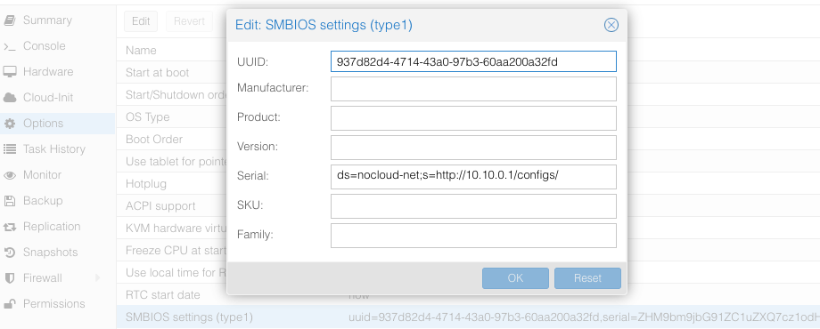
You can read the VM config from a root shell with the command qm config $ID ($ID - VM ID number of virtual machine), you will see something like:
# qm config $ID
...
smbios1: uuid=5b0f7dcf-cfe3-4bf3-87a2-1cad29bd51f9,serial=ZHM9bm9jbG91ZC1uZXQ7cz1odHRwOi8vMTAuMTAuMC4xL2NvbmZpZ3Mv,base64=1
...
Where serial holds the base64-encoded string version of ds=nocloud-net;s=http://10.10.0.1/configs/.
The serial can also be set from a root shell on the Proxmox server:
# qm set $VM --smbios1 "uuid=5b0f7dcf-cfe3-4bf3-87a2-1cad29bd51f9,serial=$(printf '%s' 'ds=nocloud-net;s=http://10.10.0.1/configs/' | base64),base64=1"
update VM 105: -smbios1 uuid=5b0f7dcf-cfe3-4bf3-87a2-1cad29bd51f9,serial=ZHM9bm9jbG91ZC1uZXQ7cz1odHRwOi8vMTAuMTAuMC4xL2NvbmZpZ3Mv,base64=1
Keep in mind that if you set the serial from the command line, you must encode it as base64, and you must include the UUID and any other settings that are already set for the smbios1 option or they will be removed.
CDROM/USB
Talos can also get machine config from local attached storage without any prior network connection being established.
You can provide configs to the server via files on a VFAT or ISO9660 filesystem.
The filesystem volume label must be cidata or CIDATA.
Example: QEMU
Create and prepare Talos machine config:
export CONTROL_PLANE_IP=192.168.1.10

talosctl gen config talos-nocloud https://$CONTROL_PLANE_IP:6443 --output-dir _out
Prepare cloud-init configs:
mkdir -p iso
mv _out/controlplane.yaml iso/user-data
echo "local-hostname: controlplane-1" > iso/meta-data
cat > iso/network-config << EOF
version: 1
config:
   - type: physical
     name: eth0
     mac_address: "52:54:00:12:34:00"
     subnets:
        - type: static
          address: 192.168.1.10
          netmask: 255.255.255.0
          gateway: 192.168.1.254
EOF
Create cloud-init iso image
cd iso && genisoimage -output cidata.iso -V cidata -r -J user-data meta-data network-config
Start the VM
qemu-system-x86_64 \
    ...
    -cdrom iso/cidata.iso \
    ...
Example: Proxmox
Proxmox can create cloud-init disk for you. Edit the cloud-init config information in Proxmox as follows, substitute your own information as necessary:
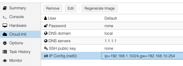
and then add a cicustom param to the virtual machine’s configuration from a root shell:
# qm set 100 --cicustom user=local:snippets/controlplane-1.yml
update VM 100: -cicustom user=local:snippets/controlplane-1.yml
Note:
snippets/controlplane-1.ymlis Talos machine config. It is usually located at/var/lib/vz/snippets/controlplane-1.yml. This file must be placed to this path manually, as Proxmox does not support snippet uploading via API/GUI.
Click on Regenerate Image button after the above changes are made.
1.3.10 - OpenStack
Creating a Cluster via the CLI
In this guide, we will create an HA Kubernetes cluster in OpenStack with 1 worker node. We will assume an existing some familiarity with OpenStack. If you need more information on OpenStack specifics, please see the official OpenStack documentation.
Environment Setup
You should have an existing openrc file. This file will provide environment variables necessary to talk to your OpenStack cloud. See here for instructions on fetching this file.
Create the Image
First, download the OpenStack image from a Talos release.
These images are called openstack-$ARCH.tar.gz.
Untar this file with tar -xvf openstack-$ARCH.tar.gz.
The resulting file will be called disk.raw.
Upload the Image
Once you have the image, you can upload to OpenStack with:
openstack image create --public --disk-format raw --file disk.raw talos
Network Infrastructure
Load Balancer and Network Ports
Once the image is prepared, you will need to work through setting up the network. Issue the following to create a load balancer, the necessary network ports for each control plane node, and associations between the two.
Creating loadbalancer:
# Create load balancer, updating vip-subnet-id if necessary
openstack loadbalancer create --name talos-control-plane --vip-subnet-id public

# Create listener
openstack loadbalancer listener create --name talos-control-plane-listener --protocol TCP --protocol-port 6443 talos-control-plane

# Pool and health monitoring
openstack loadbalancer pool create --name talos-control-plane-pool --lb-algorithm ROUND_ROBIN --listener talos-control-plane-listener --protocol TCP
openstack loadbalancer healthmonitor create --delay 5 --max-retries 4 --timeout 10 --type TCP talos-control-plane-pool
Creating ports:
# Create ports for control plane nodes, updating network name if necessary
openstack port create --network shared talos-control-plane-1
openstack port create --network shared talos-control-plane-2
openstack port create --network shared talos-control-plane-3

# Create floating IPs for the ports, so that you will have talosctl connectivity to each control plane
openstack floating ip create --port talos-control-plane-1 public
openstack floating ip create --port talos-control-plane-2 public
openstack floating ip create --port talos-control-plane-3 public
Note: Take notice of the private and public IPs associated with each of these ports, as they will be used in the next step. Additionally, take node of the port ID, as it will be used in server creation.
Associate port’s private IPs to loadbalancer:
# Create members for each port IP, updating subnet-id and address as necessary.
openstack loadbalancer member create --subnet-id shared-subnet --address <PRIVATE IP OF talos-control-plane-1 PORT> --protocol-port 6443 talos-control-plane-pool
openstack loadbalancer member create --subnet-id shared-subnet --address <PRIVATE IP OF talos-control-plane-2 PORT> --protocol-port 6443 talos-control-plane-pool
openstack loadbalancer member create --subnet-id shared-subnet --address <PRIVATE IP OF talos-control-plane-3 PORT> --protocol-port 6443 talos-control-plane-pool
Security Groups
This example uses the default security group in OpenStack. Ports have been opened to ensure that connectivity from both inside and outside the group is possible. You will want to allow, at a minimum, ports 6443 (Kubernetes API server) and 50000 (Talos API) from external sources. It is also recommended to allow communication over all ports from within the subnet.
Cluster Configuration
With our networking bits setup, we’ll fetch the IP for our load balancer and create our configuration files.
LB_PUBLIC_IP=$(openstack loadbalancer show talos-control-plane -f json | jq -r .vip_address)

talosctl gen config talos-k8s-openstack-tutorial https://${LB_PUBLIC_IP}:6443
Additionally, you can specify --config-patch with RFC6902 jsonpatch which will be applied during the config generation.
Compute Creation
We are now ready to create our OpenStack nodes.
Create control plane:
# Create control planes 2 and 3, substituting the same info.
for i in $( seq 1 3 ); do
  openstack server create talos-control-plane-$i --flavor m1.small --nic port-id=talos-control-plane-$i --image talos --user-data /path/to/controlplane.yaml
done
Create worker:
# Update network name as necessary.
openstack server create talos-worker-1 --flavor m1.small --network shared --image talos --user-data /path/to/worker.yaml
Note: This step can be repeated to add more workers.
Bootstrap Etcd
You should now be able to interact with your cluster with talosctl.
We will use one of the floating IPs we allocated earlier.
It does not matter which one.
Set the endpoints and nodes:
talosctl --talosconfig talosconfig config endpoint <control plane 1 IP>
talosctl --talosconfig talosconfig config node <control plane 1 IP>
Bootstrap etcd:
talosctl --talosconfig talosconfig bootstrap
Retrieve the kubeconfig
At this point we can retrieve the admin kubeconfig by running:
talosctl --talosconfig talosconfig kubeconfig .
1.3.11 - Oracle
Upload image
Oracle Cloud at the moment does not have a Talos official image. So you can use Bring Your Own Image (BYOI) approach.
Prepare an image for upload:
Generate an image using Image Factory.
Download the disk image artifact (e.g: https://factory.talos.dev/image/376567988ad370138ad8b2698212367b8edcb69b5fd68c80be1f2ec7d603b4ba/v1.7.6/oracle-arm64.raw.xz)
Define the image metadata file called
image_metadata.json. Example for anarm64deployment:{ "version": 2, "externalLaunchOptions": { "firmware": "UEFI_64", "networkType": "PARAVIRTUALIZED", "bootVolumeType": "PARAVIRTUALIZED", "remoteDataVolumeType": "PARAVIRTUALIZED", "localDataVolumeType": "PARAVIRTUALIZED", "launchOptionsSource": "PARAVIRTUALIZED", "pvAttachmentVersion": 2, "pvEncryptionInTransitEnabled": true, "consistentVolumeNamingEnabled": true }, "imageCapabilityData": null, "imageCapsFormatVersion": null, "operatingSystem": "Talos", "operatingSystemVersion": "1.7.6", "additionalMetadata": { "shapeCompatibilities": [ { "internalShapeName": "VM.Standard.A1.Flex", "ocpuConstraints": null, "memoryConstraints": null } ] } }Extract the xz or zst archive:
xz --decompress ./oracle-arm64.raw.xz

# or

zstd --decompress ./oracle-arm64.raw.zst
Convert the image to a
qcow2format (using qemu):qemu-img convert -f raw -O qcow2 oracle-arm64.raw oracle-arm64.qcow2Create an archive containing the image and metadata called
talos-oracle-arm64.oci:tar zcf oracle-arm64.oci oracle-arm64.qcow2 image_metadata.jsonUpload the image to a storage bucket.
Create an image, using the new URL format for the storage bucket object.
Note: file names depends on configuration of deployment such as architecture, adjust accordingly.
Talos config
OracleCloud has highly available NTP service, it can be enabled in Talos machine config with:
machine:
  time:
    servers:
      - 169.254.169.254
Creating a Cluster via the CLI
Login to the console. And open the Cloud Shell.
Create a network
export cidr_block=10.0.0.0/16
export subnet_block=10.0.0.0/24
export compartment_id=<substitute-value-of-compartment_id> # https://docs.cloud.oracle.com/en-us/iaas/tools/oci-cli/latest/oci_cli_docs/cmdref/network/vcn/create.html#cmdoption-compartment-id

export vcn_id=$(oci network vcn create --cidr-block $cidr_block --display-name talos-example --compartment-id $compartment_id --query data.id --raw-output)
export rt_id=$(oci network subnet create --cidr-block $subnet_block --display-name kubernetes --compartment-id $compartment_id --vcn-id $vcn_id --query data.route-table-id --raw-output)
export ig_id=$(oci network internet-gateway create --compartment-id $compartment_id --is-enabled true --vcn-id $vcn_id --query data.id --raw-output)

oci network route-table update --rt-id $rt_id --route-rules "[{\"cidrBlock\":\"0.0.0.0/0\",\"networkEntityId\":\"$ig_id\"}]" --force

# disable firewall
export sl_id=$(oci network vcn list --compartment-id $compartment_id --query 'data[0]."default-security-list-id"' --raw-output)

oci network security-list update --security-list-id $sl_id --egress-security-rules '[{"destination": "0.0.0.0/0", "protocol": "all", "isStateless": false}]' --ingress-security-rules '[{"source": "0.0.0.0/0", "protocol": "all", "isStateless": false}]' --force
Create a Load Balancer
Create a load balancer by issuing the commands shown below. Save the IP/DNS name, as this info will be used in the next step.
export subnet_id=$(oci network subnet list --compartment-id=$compartment_id --display-name kubernetes --query data[0].id --raw-output)
export network_load_balancer_id=$(oci nlb network-load-balancer create --compartment-id $compartment_id --display-name controlplane-lb --subnet-id $subnet_id --is-preserve-source-destination false --is-private false --query data.id --raw-output)

cat <<EOF > talos-health-checker.json
{
  "intervalInMillis": 10000,
  "port": 50000,
  "protocol": "TCP"
}
EOF

oci nlb backend-set create --health-checker file://talos-health-checker.json --name talos --network-load-balancer-id $network_load_balancer_id --policy TWO_TUPLE --is-preserve-source false
oci nlb listener create --default-backend-set-name talos --name talos --network-load-balancer-id $network_load_balancer_id --port 50000 --protocol TCP

cat <<EOF > controlplane-health-checker.json
{
  "intervalInMillis": 10000,
  "port": 6443,
  "protocol": "HTTPS",
  "returnCode": 401,
  "urlPath": "/readyz"
}
EOF

oci nlb backend-set create --health-checker file://controlplane-health-checker.json --name controlplane --network-load-balancer-id $network_load_balancer_id --policy TWO_TUPLE --is-preserve-source false
oci nlb listener create --default-backend-set-name controlplane --name controlplane --network-load-balancer-id $network_load_balancer_id --port 6443 --protocol TCP

# Save the external IP
oci nlb network-load-balancer list --compartment-id $compartment_id --display-name controlplane-lb --query 'data.items[0]."ip-addresses"'
Create the Machine Configuration Files
Generating Base Configurations
Using the IP/DNS name of the loadbalancer created earlier, generate the base configuration files for the Talos machines by issuing:
$ talosctl gen config talos-k8s-oracle-tutorial https://<load balancer IP or DNS>:6443 --additional-sans <load balancer IP or DNS>
created controlplane.yaml
created worker.yaml
created talosconfig
At this point, you can modify the generated configs to your liking.
Optionally, you can specify --config-patch with RFC6902 jsonpatches which will be applied during the config generation.
Validate the Configuration Files
Validate any edited machine configs with:
$ talosctl validate --config controlplane.yaml --mode cloud
controlplane.yaml is valid for cloud mode
$ talosctl validate --config worker.yaml --mode cloud
worker.yaml is valid for cloud mode
Create the Servers
Create the Control Plane Nodes
Create the control plane nodes with:
export shape='VM.Standard.A1.Flex'
export subnet_id=$(oci network subnet list --compartment-id=$compartment_id --display-name kubernetes --query data[0].id --raw-output)
export image_id=$(oci compute image list --compartment-id $compartment_id --shape $shape --operating-system Talos --limit 1 --query data[0].id --raw-output)
export availability_domain=$(oci iam availability-domain list --compartment-id=$compartment_id --query data[0].name --raw-output)
export network_load_balancer_id=$(oci nlb network-load-balancer list --compartment-id $compartment_id --display-name controlplane-lb --query 'data.items[0].id' --raw-output)

cat <<EOF > shape.json
{
  "memoryInGBs": 4,
  "ocpus": 1
}
EOF

export instance_id=$(oci compute instance launch --shape $shape --shape-config file://shape.json --availability-domain $availability_domain --compartment-id $compartment_id --image-id $image_id --subnet-id $subnet_id --display-name controlplane-1 --private-ip 10.0.0.11 --assign-public-ip true --launch-options '{"networkType":"PARAVIRTUALIZED"}' --user-data-file controlplane.yaml --query 'data.id' --raw-output)

oci nlb backend create --backend-set-name talos --network-load-balancer-id $network_load_balancer_id --port 50000 --target-id $instance_id
oci nlb backend create --backend-set-name controlplane --network-load-balancer-id $network_load_balancer_id --port 6443 --target-id $instance_id

export instance_id=$(oci compute instance launch --shape $shape --shape-config file://shape.json --availability-domain $availability_domain --compartment-id $compartment_id --image-id $image_id --subnet-id $subnet_id --display-name controlplane-2 --private-ip 10.0.0.12 --assign-public-ip true --launch-options '{"networkType":"PARAVIRTUALIZED"}' --user-data-file controlplane.yaml --query 'data.id' --raw-output)

oci nlb backend create --backend-set-name talos --network-load-balancer-id $network_load_balancer_id --port 50000 --target-id $instance_id
oci nlb backend create --backend-set-name controlplane --network-load-balancer-id $network_load_balancer_id --port 6443 --target-id $instance_id

export instance_id=$(oci compute instance launch --shape $shape --shape-config file://shape.json --availability-domain $availability_domain --compartment-id $compartment_id --image-id $image_id --subnet-id $subnet_id --display-name controlplane-3 --private-ip 10.0.0.13 --assign-public-ip true --launch-options '{"networkType":"PARAVIRTUALIZED"}' --user-data-file controlplane.yaml --query 'data.id' --raw-output)

oci nlb backend create --backend-set-name talos --network-load-balancer-id $network_load_balancer_id --port 50000 --target-id $instance_id
oci nlb backend create --backend-set-name controlplane --network-load-balancer-id $network_load_balancer_id --port 6443 --target-id $instance_id
Create the Worker Nodes
Create the worker nodes with the following command, repeating (and incrementing the name counter) as many times as desired.
export subnet_id=$(oci network subnet list --compartment-id=$compartment_id --display-name kubernetes --query data[0].id --raw-output)
export image_id=$(oci compute image list --compartment-id $compartment_id --operating-system Talos --limit 1 --query data[0].id --raw-output)
export availability_domain=$(oci iam availability-domain list --compartment-id=$compartment_id --query data[0].name --raw-output)
export shape='VM.Standard.E2.1.Micro'

oci compute instance launch --shape $shape --availability-domain $availability_domain --compartment-id $compartment_id --image-id $image_id --subnet-id $subnet_id --display-name worker-1 --assign-public-ip true --user-data-file worker.yaml

oci compute instance launch --shape $shape --availability-domain $availability_domain --compartment-id $compartment_id --image-id $image_id --subnet-id $subnet_id --display-name worker-2 --assign-public-ip true --user-data-file worker.yaml

oci compute instance launch --shape $shape --availability-domain $availability_domain --compartment-id $compartment_id --image-id $image_id --subnet-id $subnet_id --display-name worker-3 --assign-public-ip true --user-data-file worker.yaml
Bootstrap Etcd
To configure talosctl we will need the first control plane node’s IP.
This can be found by issuing:
export instance_id=$(oci compute instance list --compartment-id $compartment_id --display-name controlplane-1 --query 'data[0].id' --raw-output)

oci compute instance list-vnics --instance-id $instance_id --query 'data[0]."private-ip"' --raw-output
Set the endpoints and nodes for your talosconfig with:
talosctl --talosconfig talosconfig config endpoint <load balancer IP or DNS>
talosctl --talosconfig talosconfig config node <control-plane-1-IP>
Bootstrap etcd on the first control plane node with:
talosctl --talosconfig talosconfig bootstrap
Retrieve the kubeconfig
At this point we can retrieve the admin kubeconfig by running:
talosctl --talosconfig talosconfig kubeconfig .
1.3.12 - Scaleway
Talos is known to work on scaleway.com; however, it is currently undocumented.
1.3.13 - UpCloud
In this guide we will create an HA Kubernetes cluster 3 control plane nodes and 1 worker node. We assume some familiarity with UpCloud. If you need more information on UpCloud specifics, please see the official UpCloud documentation.
Create the Image
The best way to create an image for UpCloud, is to build one using
Hashicorp packer, with the
upcloud-amd64.raw.xz image found on the Talos Releases.
Using the general ISO is also possible, but the UpCloud image has some UpCloud
specific features implemented, such as the fetching of metadata and user data to configure the nodes.
To create the cluster, you need a few things locally installed:
NOTE: Make sure your account allows API connections. To do so, log into UpCloud control panel and go to People -> Account -> Permissions -> Allow API connections checkbox. It is recommended to create a separate subaccount for your API access and only set the API permission.
To use the UpCloud CLI, you need to create a config in $HOME/.config/upctl.yaml
username: your_upcloud_username
password: your_upcloud_password
To use the UpCloud packer plugin, you need to also export these credentials to your
environment variables, by e.g. putting the following in your .bashrc or .zshrc
export UPCLOUD_USERNAME="<username>"
export UPCLOUD_PASSWORD="<password>"
Next create a config file for packer to use:
# upcloud.pkr.hcl

packer {
  required_plugins {
    upcloud = {
      version = ">=v1.0.0"
      source  = "github.com/UpCloudLtd/upcloud"
    }
  }
}

variable "talos_version" {
  type    = string
  default = "v1.7.6"
}

locals {
  image = "https://github.com/siderolabs/talos/releases/download/${var.talos_version}/upcloud-amd64.raw.xz"
}

variable "username" {
  type        = string
  description = "UpCloud API username"
  default     = "${env("UPCLOUD_USERNAME")}"
}

variable "password" {
  type        = string
  description = "UpCloud API password"
  default     = "${env("UPCLOUD_PASSWORD")}"
  sensitive   = true
}

source "upcloud" "talos" {
  username        = "${var.username}"
  password        = "${var.password}"
  zone            = "us-nyc1"
  storage_name    = "Debian GNU/Linux 11 (Bullseye)"
  template_name   = "Talos (${var.talos_version})"
}

build {
  sources = ["source.upcloud.talos"]

  provisioner "shell" {
    inline = [
      "apt-get install -y wget xz-utils",
      "wget -q -O /tmp/talos.raw.xz ${local.image}",
      "xz -d -c /tmp/talos.raw.xz | dd of=/dev/vda",
    ]
  }

  provisioner "shell-local" {
      inline = [
      "upctl server stop --type hard custom",
      ]
  }
}
Now create a new image by issuing the commands shown below.
packer init .
packer build .
After doing this, you can find the custom image in the console interface under storage.
Creating a Cluster via the CLI
Create an Endpoint
To communicate with the Talos cluster you will need a single endpoint that is used to access the cluster. This can either be a loadbalancer that will sit in front of all your control plane nodes, a DNS name with one or more A or AAAA records pointing to the control plane nodes, or directly the IP of a control plane node.
Which option is best for you will depend on your needs. Endpoint selection has been further documented here.
After you decide on which endpoint to use, note down the domain name or IP, as we will need it in the next step.
Create the Machine Configuration Files
Generating Base Configurations
Using the DNS name of the endpoint created earlier, generate the base configuration files for the Talos machines:
$ talosctl gen config talos-upcloud-tutorial https://<load balancer IP or DNS>:<port> --install-disk /dev/vda
created controlplane.yaml
created worker.yaml
created talosconfig
At this point, you can modify the generated configs to your liking. Depending on the Kubernetes version you want to run, you might need to select a different Talos version, as not all versions are compatible. You can find the support matrix here.
Optionally, you can specify --config-patch with RFC6902 jsonpatch or yamlpatch
which will be applied during the config generation.
Validate the Configuration Files
$ talosctl validate --config controlplane.yaml --mode cloud
controlplane.yaml is valid for cloud mode
$ talosctl validate --config worker.yaml --mode cloud
worker.yaml is valid for cloud mode
Create the Servers
Create the Control Plane Nodes
Run the following to create three total control plane nodes:
for ID in $(seq 3); do
    upctl server create \
      --zone us-nyc1 \
      --title talos-us-nyc1-master-$ID \
      --hostname talos-us-nyc1-master-$ID \
      --plan 2xCPU-4GB \
      --os "Talos (v1.7.6)" \
      --user-data "$(cat controlplane.yaml)" \
      --enable-metada
done
Note: modify the zone and OS depending on your preferences. The OS should match the template name generated with packer in the previous step.
Note the IP address of the first control plane node, as we will need it later.
Create the Worker Nodes
Run the following to create a worker node:
upctl server create \
  --zone us-nyc1 \
  --title talos-us-nyc1-worker-1 \
  --hostname talos-us-nyc1-worker-1 \
  --plan 2xCPU-4GB \
  --os "Talos (v1.7.6)" \
  --user-data "$(cat worker.yaml)" \
  --enable-metada
Bootstrap Etcd
To configure talosctl we will need the first control plane node’s IP, as noted earlier.
We only add one node IP, as that is the entry into our cluster against which our commands will be run.
All requests to other nodes are proxied through the endpoint, and therefore not
all nodes need to be manually added to the config.
You don’t want to run your commands against all nodes, as this can destroy your
cluster if you are not careful (further documentation).
Set the endpoints and nodes:
talosctl --talosconfig talosconfig config endpoint <control plane 1 IP>
talosctl --talosconfig talosconfig config node <control plane 1 IP>
Bootstrap etcd:
talosctl --talosconfig talosconfig bootstrap
Retrieve the kubeconfig
At this point we can retrieve the admin kubeconfig by running:
talosctl --talosconfig talosconfig kubeconfig
It will take a few minutes before Kubernetes has been fully bootstrapped, and is accessible.
You can check if the nodes are registered in Talos by running
talosctl --talosconfig talosconfig get members
To check if your nodes are ready, run
kubectl get nodes
1.3.14 - Vultr
Creating a Cluster using the Vultr CLI
This guide will demonstrate how to create a highly-available Kubernetes cluster with one worker using the Vultr cloud provider.
Vultr have a very well documented REST API, and an open-source CLI tool to interact with the API which will be used in this guide.
Make sure to follow installation and authentication instructions for the vultr-cli tool.
Boot Options
Upload an ISO Image
First step is to make the Talos ISO available to Vultr by uploading the latest release of the ISO to the Vultr ISO server.
vultr-cli iso create --url https://github.com/siderolabs/talos/releases/download/v1.7.6/metal-amd64.iso
Make a note of the ID in the output, it will be needed later when creating the instances.
PXE Booting via Image Factory
Talos Linux can be PXE-booted on Vultr using Image Factory, using the vultr platform: e.g.
https://pxe.factory.talos.dev/pxe/376567988ad370138ad8b2698212367b8edcb69b5fd68c80be1f2ec7d603b4ba/v1.7.6/vultr-amd64 (this URL references the default schematic and amd64 architecture).
Create a Load Balancer
A load balancer is needed to serve as the Kubernetes endpoint for the cluster.
vultr-cli load-balancer create \
   --region $REGION \
   --label "Talos Kubernetes Endpoint" \
   --port 6443 \
   --protocol tcp \
   --check-interval 10 \
   --response-timeout 5 \
   --healthy-threshold 5 \
   --unhealthy-threshold 3 \
   --forwarding-rules frontend_protocol:tcp,frontend_port:443,backend_protocol:tcp,backend_port:6443
Make a note of the ID of the load balancer from the output of the above command, it will be needed after the control plane instances are created.
vultr-cli load-balancer get $LOAD_BALANCER_ID | grep ^IP
Make a note of the IP address, it will be needed later when generating the configuration.
Create the Machine Configuration
Generate Base Configuration
Using the IP address (or DNS name if one was created) of the load balancer created above, generate the machine configuration files for the new cluster.
talosctl gen config talos-kubernetes-vultr https://$LOAD_BALANCER_ADDRESS
Once generated, the machine configuration can be modified as necessary for the new cluster, for instance updating disk installation, or adding SANs for the certificates.
Validate the Configuration Files
talosctl validate --config controlplane.yaml --mode cloud
talosctl validate --config worker.yaml --mode cloud
Create the Nodes
Create the Control Plane Nodes
First a control plane needs to be created, with the example below creating 3 instances in a loop.
The instance type (noted by the --plan vc2-2c-4gb argument) in the example is for a minimum-spec control plane node, and should be updated to suit the cluster being created.
for id in $(seq 3); do
    vultr-cli instance create \
        --plan vc2-2c-4gb \
        --region $REGION \
        --iso $TALOS_ISO_ID \
        --host talos-k8s-cp${id} \
        --label "Talos Kubernetes Control Plane" \
        --tags talos,kubernetes,control-plane
done
Make a note of the instance IDs, as they are needed to attach to the load balancer created earlier.
vultr-cli load-balancer update $LOAD_BALANCER_ID --instances $CONTROL_PLANE_1_ID,$CONTROL_PLANE_2_ID,$CONTROL_PLANE_3_ID
Once the nodes are booted and waiting in maintenance mode, the machine configuration can be applied to each one in turn.
talosctl --talosconfig talosconfig apply-config --insecure --nodes $CONTROL_PLANE_1_ADDRESS --file controlplane.yaml
talosctl --talosconfig talosconfig apply-config --insecure --nodes $CONTROL_PLANE_2_ADDRESS --file controlplane.yaml
talosctl --talosconfig talosconfig apply-config --insecure --nodes $CONTROL_PLANE_3_ADDRESS --file controlplane.yaml
Create the Worker Nodes
Now worker nodes can be created and configured in a similar way to the control plane nodes, the difference being mainly in the machine configuration file.
Note that like with the control plane nodes, the instance type (here set by --plan vc2-1-1gb) should be changed for the actual cluster requirements.
for id in $(seq 1); do
    vultr-cli instance create \
        --plan vc2-1c-1gb \
        --region $REGION \
        --iso $TALOS_ISO_ID \
        --host talos-k8s-worker${id} \
        --label "Talos Kubernetes Worker" \
        --tags talos,kubernetes,worker
done
Once the worker is booted and in maintenance mode, the machine configuration can be applied in the following manner.
talosctl --talosconfig talosconfig apply-config --insecure --nodes $WORKER_1_ADDRESS --file worker.yaml
Bootstrap etcd
Once all the cluster nodes are correctly configured, the cluster can be bootstrapped to become functional.
It is important that the talosctl bootstrap command be executed only once and against only a single control plane node.
talosctl --talosconfig talosconfig boostrap --endpoints $CONTROL_PLANE_1_ADDRESS --nodes $CONTROL_PLANE_1_ADDRESS
Configure Endpoints and Nodes
While the cluster goes through the bootstrapping process and beings to self-manage, the talosconfig can be updated with the endpoints and nodes.
talosctl --talosconfig talosconfig config endpoints $CONTROL_PLANE_1_ADDRESS $CONTROL_PLANE_2_ADDRESS $CONTROL_PLANE_3_ADDRESS
talosctl --talosconfig talosconfig config nodes $CONTROL_PLANE_1_ADDRESS $CONTROL_PLANE_2_ADDRESS $CONTROL_PLANE_3_ADDRESS WORKER_1_ADDRESS
Retrieve the kubeconfig
Finally, with the cluster fully running, the administrative kubeconfig can be retrieved from the Talos API to be saved locally.
talosctl --talosconfig talosconfig kubeconfig .
Now the kubeconfig can be used by any of the usual Kubernetes tools to interact with the Talos-based Kubernetes cluster as normal.
1.4 - Local Platforms
1.4.1 - Docker
In this guide we will create a Kubernetes cluster in Docker, using a containerized version of Talos.
Running Talos in Docker is intended to be used in CI pipelines, and local testing when you need a quick and easy cluster. Furthermore, if you are running Talos in production, it provides an excellent way for developers to develop against the same version of Talos.
Requirements
The follow are requirements for running Talos in Docker:
- Docker 18.03 or greater
- a recent version of
talosctl
Note
If you are using Docker Desktop on a macOS computer, and you encounter the error: Cannot connect to the Docker daemon at unix:///var/run/docker.sock. Is the docker daemon running? you may need to manually create the link for the Docker socket:sudo ln -s "$HOME/.docker/run/docker.sock" /var/run/docker.sockCaveats
Due to the fact that Talos will be running in a container, certain APIs are not available.
For example upgrade, reset, and similar APIs don’t apply in container mode.
Further, when running on a Mac in docker, due to networking limitations, VIPs are not supported.
Create the Cluster
Creating a local cluster is as simple as:
talosctl cluster create
Once the above finishes successfully, your talosconfig (~/.talos/config) and kubeconfig (~/.kube/config) will be configured to point to the new cluster.
Note: Startup times can take up to a minute or more before the cluster is available.
Finally, we just need to specify which nodes you want to communicate with using talosctl. Talosctl can operate on one or all the nodes in the cluster – this makes cluster wide commands much easier.
talosctl config nodes 10.5.0.2 10.5.0.3
Talos and Kubernetes API are mapped to a random port on the host machine, the retrieved talosconfig and kubeconfig are configured automatically to point to the new cluster.
Talos API endpoint can be found using talosctl config info:
$ talosctl config info
...
Endpoints:           127.0.0.1:38423
Kubernetes API endpoint is available with talosctl cluster show:
$ talosctl cluster show
...
KUBERNETES ENDPOINT   https://127.0.0.1:43083
Using the Cluster
Once the cluster is available, you can make use of talosctl and kubectl to interact with the cluster.
For example, to view current running containers, run talosctl containers for a list of containers in the system namespace, or talosctl containers -k for the k8s.io namespace.
To view the logs of a container, use talosctl logs <container> or talosctl logs -k <container>.
Cleaning Up
To cleanup, run:
talosctl cluster destroy
Multiple Clusters
Multiple Talos Linux cluster can be created on the same host, each cluster will need to have:
- a unique name (default is
talos-default) - a unique network CIDR (default is
10.5.0.0/24)
To create a new cluster, run:
talosctl cluster create --name cluster2 --cidr 10.6.0.0/24
To destroy a specific cluster, run:
talosctl cluster destroy --name cluster2
To switch between clusters, use --context flag:
talosctl --context cluster2 version
kubectl --context admin@cluster2 get nodes
Running Talos in Docker Manually
To run Talos in a container manually, run:
docker run --rm -it \
  --name tutorial \
  --hostname talos-cp \
  --read-only \
  --privileged \
  --security-opt seccomp=unconfined \
  --mount type=tmpfs,destination=/run \
  --mount type=tmpfs,destination=/system \
  --mount type=tmpfs,destination=/tmp \
  --mount type=volume,destination=/system/state \
  --mount type=volume,destination=/var \
  --mount type=volume,destination=/etc/cni \
  --mount type=volume,destination=/etc/kubernetes \
  --mount type=volume,destination=/usr/libexec/kubernetes \
  --mount type=volume,destination=/opt \
  -e PLATFORM=container \
  ghcr.io/siderolabs/talos:v1.7.6
The machine configuration submitted to the container should have a host DNS feature enabled with forwardKubeDNSToHost enabled.
It is used to forward DNS requests to the resolver provided by Docker (or other container runtime).
1.4.2 - QEMU
In this guide we will create a Kubernetes cluster using QEMU.
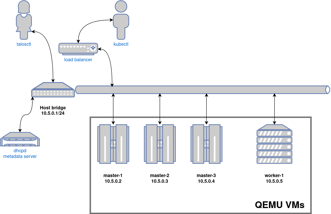
Video Walkthrough
To see a live demo of this writeup, see the video below:
Requirements
- Linux
- a kernel with
- KVM enabled (
/dev/kvmmust exist) CONFIG_NET_SCH_NETEMenabledCONFIG_NET_SCH_INGRESSenabled
- KVM enabled (
- at least
CAP_SYS_ADMINandCAP_NET_ADMINcapabilities - QEMU
bridge,staticandfirewallCNI plugins from the standard CNI plugins, andtc-redirect-tapCNI plugin from the awslabs tc-redirect-tap installed to/opt/cni/bin(installed automatically bytalosctl)- iptables
/var/run/netnsdirectory should exist
Installation
How to get QEMU
Install QEMU with your operating system package manager. For example, on Ubuntu for x86:
apt install qemu-system-x86 qemu-kvm
Install talosctl
You can download talosctl an MacOS and Linux via:
brew install siderolabs/tap/talosctl
For manually installation and other platform please see the talosctl installation guide.
Install Talos kernel and initramfs
QEMU provisioner depends on Talos kernel (vmlinuz) and initramfs (initramfs.xz).
These files can be downloaded from the Talos release:
mkdir -p _out/
curl https://github.com/siderolabs/talos/releases/download/<version>/vmlinuz-<arch> -L -o _out/vmlinuz-<arch>
curl https://github.com/siderolabs/talos/releases/download/<version>/initramfs-<arch>.xz -L -o _out/initramfs-<arch>.xz
For example version v1.7.6:
curl https://github.com/siderolabs/talos/releases/download/v1.7.6/vmlinuz-amd64 -L -o _out/vmlinuz-amd64
curl https://github.com/siderolabs/talos/releases/download/v1.7.6/initramfs-amd64.xz -L -o _out/initramfs-amd64.xz
Create the Cluster
For the first time, create root state directory as your user so that you can inspect the logs as non-root user:
mkdir -p ~/.talos/clusters
Create the cluster:
sudo --preserve-env=HOME talosctl cluster create --provisioner qemu
Before the first cluster is created, talosctl will download the CNI bundle for the VM provisioning and install it to ~/.talos/cni directory.
Once the above finishes successfully, your talosconfig (~/.talos/config) will be configured to point to the new cluster, and kubeconfig will be
downloaded and merged into default kubectl config location (~/.kube/config).
Cluster provisioning process can be optimized with registry pull-through caches.
Using the Cluster
Once the cluster is available, you can make use of talosctl and kubectl to interact with the cluster.
For example, to view current running containers, run talosctl -n 10.5.0.2 containers for a list of containers in the system namespace, or talosctl -n 10.5.0.2 containers -k for the k8s.io namespace.
To view the logs of a container, use talosctl -n 10.5.0.2 logs <container> or talosctl -n 10.5.0.2 logs -k <container>.
A bridge interface will be created, and assigned the default IP 10.5.0.1. Each node will be directly accessible on the subnet specified at cluster creation time. A loadbalancer runs on 10.5.0.1 by default, which handles loadbalancing for the Kubernetes APIs.
You can see a summary of the cluster state by running:
$ talosctl cluster show --provisioner qemu
PROVISIONER       qemu
NAME              talos-default
NETWORK NAME      talos-default
NETWORK CIDR      10.5.0.0/24
NETWORK GATEWAY   10.5.0.1
NETWORK MTU       1500

NODES:

NAME                           TYPE           IP         CPU    RAM      DISK
talos-default-controlplane-1   ControlPlane   10.5.0.2   1.00   1.6 GB   4.3 GB
talos-default-controlplane-2   ControlPlane   10.5.0.3   1.00   1.6 GB   4.3 GB
talos-default-controlplane-3   ControlPlane   10.5.0.4   1.00   1.6 GB   4.3 GB
talos-default-worker-1         Worker         10.5.0.5   1.00   1.6 GB   4.3 GB
Cleaning Up
To cleanup, run:
sudo --preserve-env=HOME talosctl cluster destroy --provisioner qemu
Note: In that case that the host machine is rebooted before destroying the cluster, you may need to manually remove
~/.talos/clusters/talos-default.
Manual Clean Up
The talosctl cluster destroy command depends heavily on the clusters state directory.
It contains all related information of the cluster.
The PIDs and network associated with the cluster nodes.
If you happened to have deleted the state folder by mistake or you would like to cleanup the environment, here are the steps how to do it manually:
Remove VM Launchers
Find the process of talosctl qemu-launch:
ps -elf | grep 'talosctl qemu-launch'
To remove the VMs manually, execute:
sudo kill -s SIGTERM <PID>
Example output, where VMs are running with PIDs 157615 and 157617
ps -elf | grep '[t]alosctl qemu-launch'
0 S root      157615    2835  0  80   0 - 184934 -     07:53 ?        00:00:00 talosctl qemu-launch
0 S root      157617    2835  0  80   0 - 185062 -     07:53 ?        00:00:00 talosctl qemu-launch
sudo kill -s SIGTERM 157615
sudo kill -s SIGTERM 157617
Stopping VMs
Find the process of qemu-system:
ps -elf | grep 'qemu-system'
To stop the VMs manually, execute:
sudo kill -s SIGTERM <PID>
Example output, where VMs are running with PIDs 158065 and 158216
ps -elf | grep qemu-system
2 S root     1061663 1061168 26  80   0 - 1786238 -    14:05 ?        01:53:56 qemu-system-x86_64 -m 2048 -drive format=raw,if=virtio,file=/home/username/.talos/clusters/talos-default/bootstrap-master.disk -smp cpus=2 -cpu max -nographic -netdev tap,id=net0,ifname=tap0,script=no,downscript=no -device virtio-net-pci,netdev=net0,mac=1e:86:c6:b4:7c:c4 -device virtio-rng-pci -no-reboot -boot order=cn,reboot-timeout=5000 -smbios type=1,uuid=7ec0a73c-826e-4eeb-afd1-39ff9f9160ca -machine q35,accel=kvm
2 S root     1061663 1061170 67  80   0 - 621014 -     21:23 ?        00:00:07 qemu-system-x86_64 -m 2048 -drive format=raw,if=virtio,file=/homeusername/.talos/clusters/talos-default/pxe-1.disk -smp cpus=2 -cpu max -nographic -netdev tap,id=net0,ifname=tap0,script=no,downscript=no -device virtio-net-pci,netdev=net0,mac=36:f3:2f:c3:9f:06 -device virtio-rng-pci -no-reboot -boot order=cn,reboot-timeout=5000 -smbios type=1,uuid=ce12a0d0-29c8-490f-b935-f6073ab916a6 -machine q35,accel=kvm
sudo kill -s SIGTERM 1061663
sudo kill -s SIGTERM 1061663
Remove load balancer
Find the process of talosctl loadbalancer-launch:
ps -elf | grep 'talosctl loadbalancer-launch'
To remove the LB manually, execute:
sudo kill -s SIGTERM <PID>
Example output, where loadbalancer is running with PID 157609
ps -elf | grep '[t]alosctl loadbalancer-launch'
4 S root      157609    2835  0  80   0 - 184998 -     07:53 ?        00:00:07 talosctl loadbalancer-launch --loadbalancer-addr 10.5.0.1 --loadbalancer-upstreams 10.5.0.2
sudo kill -s SIGTERM 157609
Remove DHCP server
Find the process of talosctl dhcpd-launch:
ps -elf | grep 'talosctl dhcpd-launch'
To remove the LB manually, execute:
sudo kill -s SIGTERM <PID>
Example output, where loadbalancer is running with PID 157609
ps -elf | grep '[t]alosctl dhcpd-launch'
4 S root      157609    2835  0  80   0 - 184998 -     07:53 ?        00:00:07 talosctl dhcpd-launch --state-path /home/username/.talos/clusters/talos-default --addr 10.5.0.1 --interface talosbd9c32bc
sudo kill -s SIGTERM 157609
Remove network
This is more tricky part as if you have already deleted the state folder.
If you didn’t then it is written in the state.yaml in the
~/.talos/clusters/<cluster-name> directory.
sudo cat ~/.talos/clusters/<cluster-name>/state.yaml | grep bridgename
bridgename: talos<uuid>
If you only had one cluster, then it will be the interface with name
talos<uuid>
46: talos<uuid>: <NO-CARRIER,BROADCAST,MULTICAST,UP> mtu 1500 qdisc noqueue state DOWN group default qlen 1000
    link/ether a6:72:f4:0a:d3:9c brd ff:ff:ff:ff:ff:ff
    inet 10.5.0.1/24 brd 10.5.0.255 scope global talos17c13299
       valid_lft forever preferred_lft forever
    inet6 fe80::a472:f4ff:fe0a:d39c/64 scope link
       valid_lft forever preferred_lft forever
To remove this interface:
sudo ip link del talos<uuid>
Remove state directory
To remove the state directory execute:
sudo rm -Rf /home/$USER/.talos/clusters/<cluster-name>
Troubleshooting
Logs
Inspect logs directory
sudo cat ~/.talos/clusters/<cluster-name>/*.log
Logs are saved under <cluster-name>-<role>-<node-id>.log
For example in case of k8s cluster name:
ls -la ~/.talos/clusters/k8s | grep log
-rw-r--r--. 1 root root      69415 Apr 26 20:58 k8s-master-1.log
-rw-r--r--. 1 root root      68345 Apr 26 20:58 k8s-worker-1.log
-rw-r--r--. 1 root root      24621 Apr 26 20:59 lb.log
Inspect logs during the installation
tail -f ~/.talos/clusters/<cluster-name>/*.log
1.4.3 - VirtualBox
In this guide we will create a Kubernetes cluster using VirtualBox.
Video Walkthrough
To see a live demo of this writeup, visit Youtube here:
Installation
How to Get VirtualBox
Install VirtualBox with your operating system package manager or from the website. For example, on Ubuntu for x86:
apt install virtualbox
Install talosctl
You can download talosctl an MacOS and Linux via:
brew install siderolabs/tap/talosctl
For manually installation and other platform please see the talosctl installation guide.
Download ISO Image
Download the ISO image from the Talos release page.
You can download metal-amd64.iso via
github.com/siderolabs/talos/releases
mkdir -p _out/
curl https://github.com/siderolabs/talos/releases/download/<version>/metal-<arch>.iso -L -o _out/metal-<arch>.iso
For example version v1.7.6 for linux platform:
mkdir -p _out/
curl https://github.com/siderolabs/talos/releases/download/v1.7.6/metal-amd64.iso -L -o _out/metal-amd64.iso
Create VMs
Start by creating a new VM by clicking the “New” button in the VirtualBox UI:
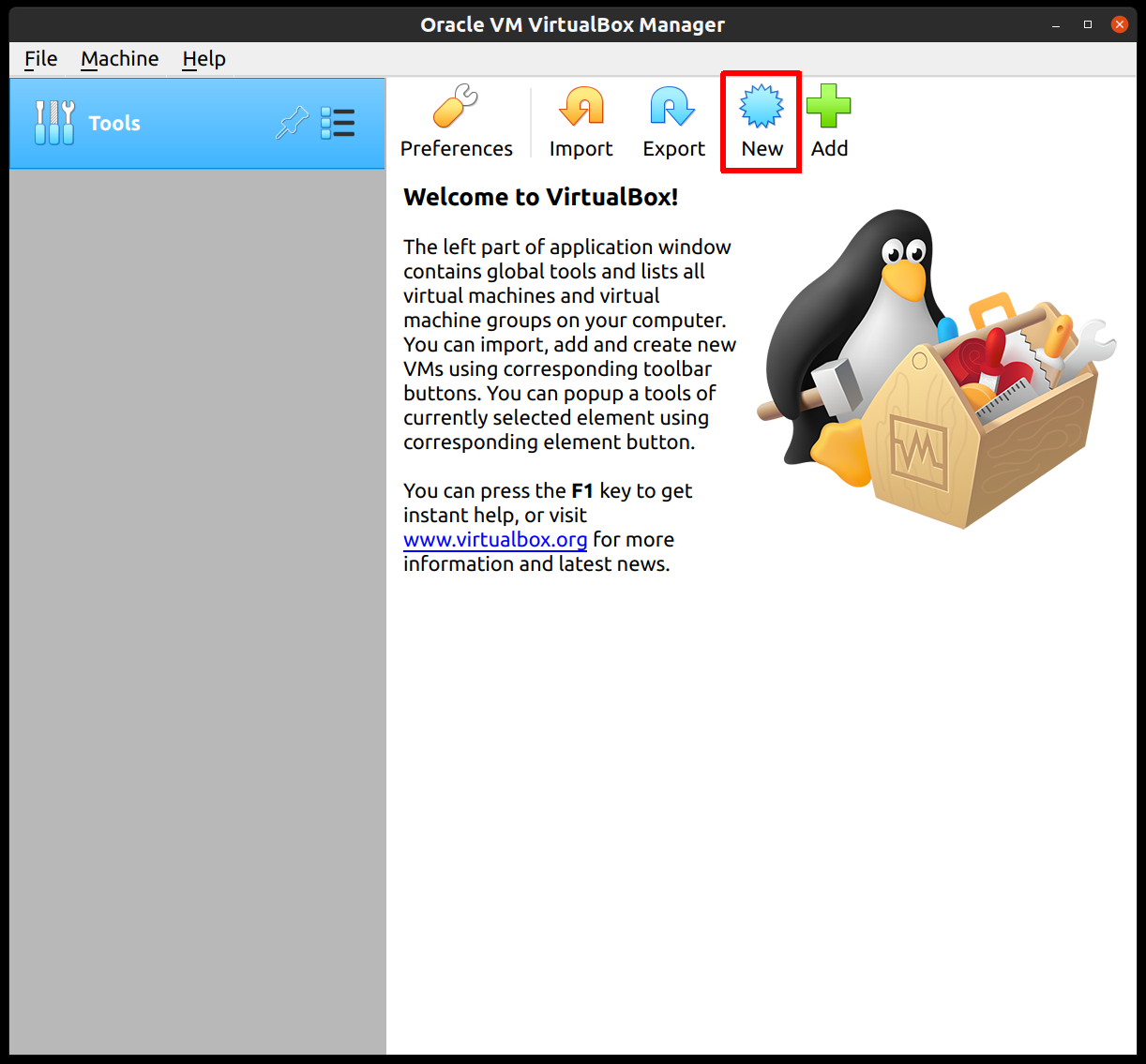
Supply a name for this VM, and specify the Type and Version:
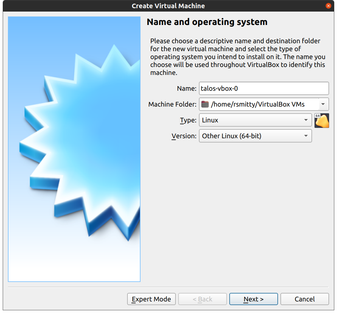
Edit the memory to supply at least 2GB of RAM for the VM:
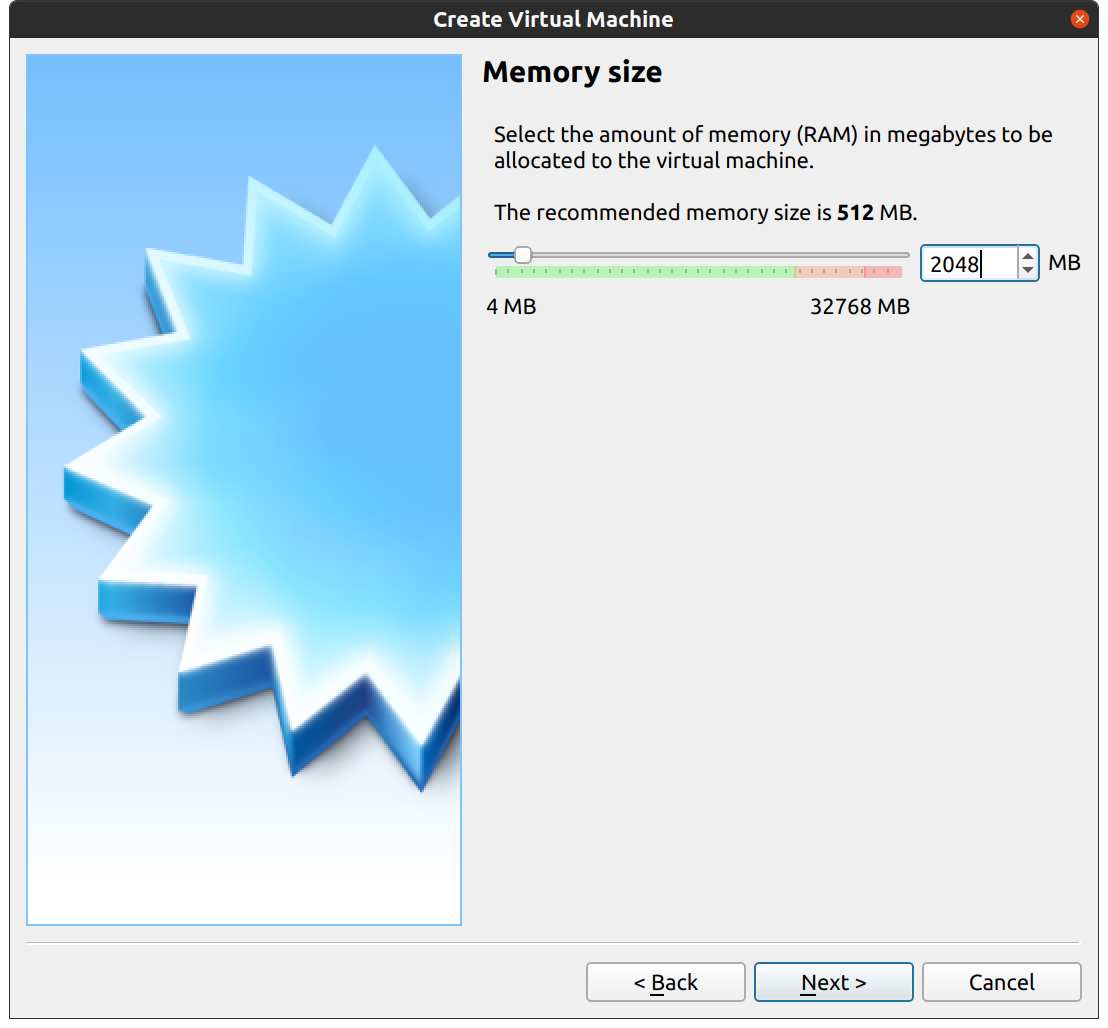
Proceed through the disk settings, keeping the defaults. You can increase the disk space if desired.
Once created, select the VM and hit “Settings”:
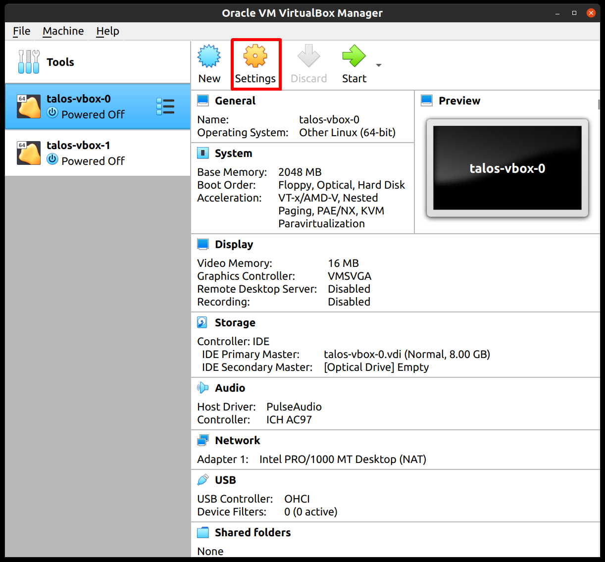
In the “System” section, supply at least 2 CPUs:
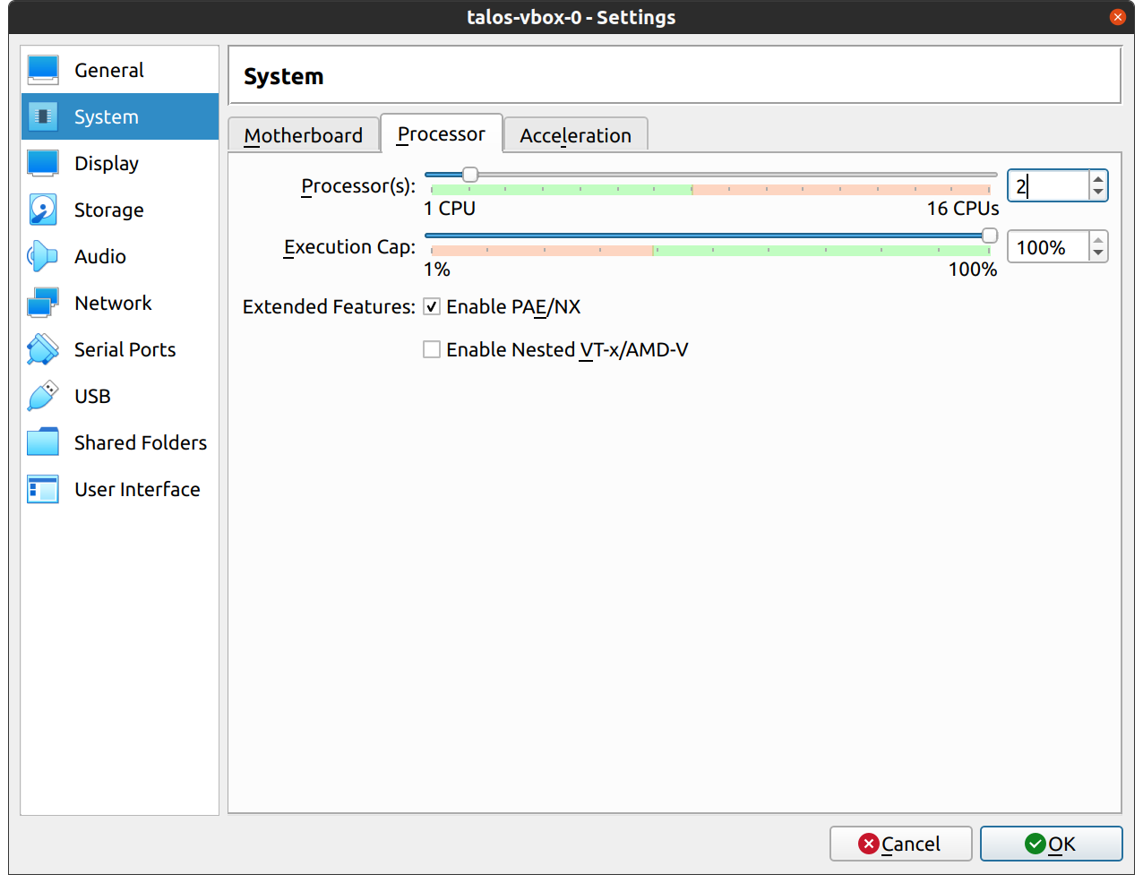
In the “Network” section, switch the network “Attached To” section to “Bridged Adapter”:
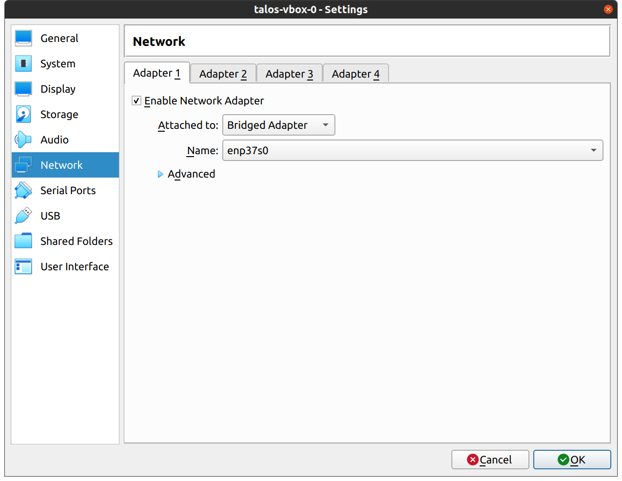
Finally, in the “Storage” section, select the optical drive and, on the right, select the ISO by browsing your filesystem:
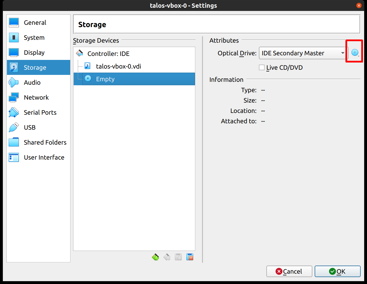
Repeat this process for a second VM to use as a worker node. You can also repeat this for additional nodes desired.
Start Control Plane Node
Once the VMs have been created and updated, start the VM that will be the first control plane node.
This VM will boot the ISO image specified earlier and enter “maintenance mode”.
Once the machine has entered maintenance mode, there will be a console log that details the IP address that the node received.
Take note of this IP address, which will be referred to as $CONTROL_PLANE_IP for the rest of this guide.
If you wish to export this IP as a bash variable, simply issue a command like export CONTROL_PLANE_IP=1.2.3.4.
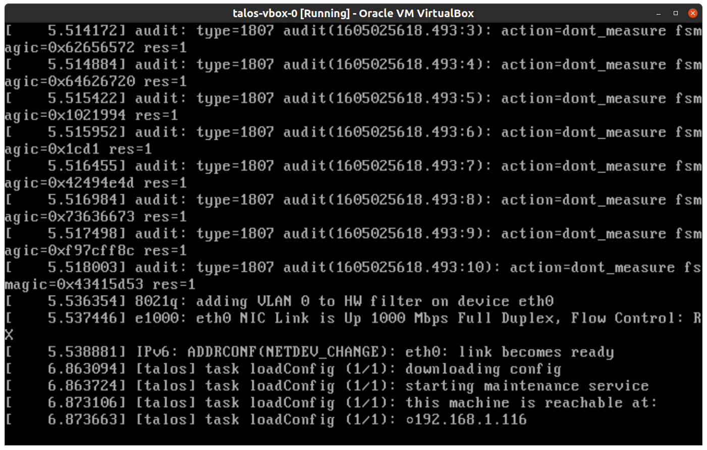
Generate Machine Configurations
With the IP address above, you can now generate the machine configurations to use for installing Talos and Kubernetes. Issue the following command, updating the output directory, cluster name, and control plane IP as you see fit:
talosctl gen config talos-vbox-cluster https://$CONTROL_PLANE_IP:6443 --output-dir _out
This will create several files in the _out directory: controlplane.yaml, worker.yaml, and talosconfig.
Create Control Plane Node
Using the controlplane.yaml generated above, you can now apply this config using talosctl.
Issue:
talosctl apply-config --insecure --nodes $CONTROL_PLANE_IP --file _out/controlplane.yaml
You should now see some action in the VirtualBox console for this VM. Talos will be installed to disk, the VM will reboot, and then Talos will configure the Kubernetes control plane on this VM.
Note: This process can be repeated multiple times to create an HA control plane.
Create Worker Node
Create at least a single worker node using a process similar to the control plane creation above.
Start the worker node VM and wait for it to enter “maintenance mode”.
Take note of the worker node’s IP address, which will be referred to as $WORKER_IP
Issue:
talosctl apply-config --insecure --nodes $WORKER_IP --file _out/worker.yaml
Note: This process can be repeated multiple times to add additional workers.
Using the Cluster
Once the cluster is available, you can make use of talosctl and kubectl to interact with the cluster.
For example, to view current running containers, run talosctl containers for a list of containers in the system namespace, or talosctl containers -k for the k8s.io namespace.
To view the logs of a container, use talosctl logs <container> or talosctl logs -k <container>.
First, configure talosctl to talk to your control plane node by issuing the following, updating paths and IPs as necessary:
export TALOSCONFIG="_out/talosconfig"
talosctl config endpoint $CONTROL_PLANE_IP
talosctl config node $CONTROL_PLANE_IP
Bootstrap Etcd
Set the endpoints and nodes:
talosctl --talosconfig $TALOSCONFIG config endpoint <control plane 1 IP>
talosctl --talosconfig $TALOSCONFIG config node <control plane 1 IP>
Bootstrap etcd:
talosctl --talosconfig $TALOSCONFIG bootstrap
Retrieve the kubeconfig
At this point we can retrieve the admin kubeconfig by running:
talosctl --talosconfig $TALOSCONFIG kubeconfig .
You can then use kubectl in this fashion:
kubectl get nodes
Cleaning Up
To cleanup, simply stop and delete the virtual machines from the VirtualBox UI.
1.5 - Single Board Computers
1.5.1 - Banana Pi M64
Prerequisites
You will need
talosctl- an SD card
Download the latest talosctl.
curl -Lo /usr/local/bin/talosctl https://github.com/siderolabs/talos/releases/download/v1.7.6/talosctl-$(uname -s | tr "[:upper:]" "[:lower:]")-amd64
chmod +x /usr/local/bin/talosctl
Download the Image using Image Factory
The default schematic id for “vanilla” Banana Pi M64 is 8e11dcb3c2803fbe893ab201fcadf1ef295568410e7ced95c6c8b122a5070ce4.
Refer to the Image Factory documentation for more information.
Download the image and decompress it:
curl -LO https://factory.talos.dev/image/8e11dcb3c2803fbe893ab201fcadf1ef295568410e7ced95c6c8b122a5070ce4/v1.7.6/metal-arm64.raw.xz
xz -d metal-arm64.raw.xz
Writing the Image
The path to your SD card can be found using fdisk on Linux or diskutil on macOS.
In this example, we will assume /dev/mmcblk0.
Now dd the image to your SD card:
sudo dd if=metal-arm64.raw of=/dev/mmcblk0 conv=fsync bs=4M
Bootstrapping the Node
Insert the SD card to your board, turn it on and wait for the console to show you the instructions for bootstrapping the node. Following the instructions in the console output to connect to the interactive installer:
talosctl apply-config --insecure --mode=interactive --nodes <node IP or DNS name>
Once the interactive installation is applied, the cluster will form and you can then use kubectl.
Retrieve the kubeconfig
Retrieve the admin kubeconfig by running:
talosctl kubeconfig
Upgrading
For example, to upgrade to the latest version of Talos, you can run:
talosctl -n <node IP or DNS name> upgrade --image=factory.talos.dev/installer/8e11dcb3c2803fbe893ab201fcadf1ef295568410e7ced95c6c8b122a5070ce4:v1.7.6
1.5.2 - Friendlyelec Nano PI R4S
Prerequisites
You will need
talosctl- an SD card
Download the latest talosctl.
curl -Lo /usr/local/bin/talosctl https://github.com/siderolabs/talos/releases/download/v1.7.6/talosctl-$(uname -s | tr "[:upper:]" "[:lower:]")-amd64
chmod +x /usr/local/bin/talosctl
Download the Image
The default schematic id for “vanilla” NanoPi R4S is 5f74a09891d5830f0b36158d3d9ea3b1c9cc019848ace08ff63ba255e38c8da4.
Refer to the Image Factory documentation for more information.
Download the image and decompress it:
curl -LO https://factory.talos.dev/image/5f74a09891d5830f0b36158d3d9ea3b1c9cc019848ace08ff63ba255e38c8da4/v1.7.6/metal-arm64.raw.xz
xz -d metal-arm64.raw.xz
Writing the Image
The path to your SD card can be found using fdisk on Linux or diskutil on macOS.
In this example, we will assume /dev/mmcblk0.
Now dd the image to your SD card:
sudo dd if=metal-arm64.raw of=/dev/mmcblk0 conv=fsync bs=4M
Bootstrapping the Node
Insert the SD card to your board, turn it on and wait for the console to show you the instructions for bootstrapping the node. Following the instructions in the console output to connect to the interactive installer:
talosctl apply-config --insecure --mode=interactive --nodes <node IP or DNS name>
Once the interactive installation is applied, the cluster will form and you can then use kubectl.
Retrieve the kubeconfig
Retrieve the admin kubeconfig by running:
talosctl kubeconfig
Upgrading
For example, to upgrade to the latest version of Talos, you can run:
talosctl -n <node IP or DNS name> upgrade --image=factory.talos.dev/installer/5f74a09891d5830f0b36158d3d9ea3b1c9cc019848ace08ff63ba255e38c8da4:v1.7.6
1.5.3 - Jetson Nano
Prerequisites
You will need
talosctl- an SD card/USB drive
- crane CLI
Download the latest talosctl.
curl -Lo /usr/local/bin/talosctl https://github.com/siderolabs/talos/releases/download/v1.7.6/talosctl-$(uname -s | tr "[:upper:]" "[:lower:]")-amd64
chmod +x /usr/local/bin/talosctl
Flashing the firmware to on-board SPI flash
Flashing the firmware only needs to be done once.
We will use the R32.7.2 release for the Jetson Nano.
Most of the instructions is similar to this doc except that we’d be using a upstream version of u-boot with patches from NVIDIA u-boot so that USB boot also works.
Before flashing we need the following:
- A USB-A to micro USB cable
- A jumper wire to enable recovery mode
- A HDMI monitor to view the logs if the USB serial adapter is not available
- A USB to Serial adapter with 3.3V TTL (optional)
- A 5V DC barrel jack
If you’re planning to use the serial console follow the documentation here
First start by downloading the Jetson Nano L4T release.
curl -SLO https://developer.nvidia.com/embedded/l4t/r32_release_v7.1/t210/jetson-210_linux_r32.7.2_aarch64.tbz2
Next we will extract the L4T release and replace the u-boot binary with the patched version.
tar xf jetson-210_linux_r32.6.1_aarch64.tbz2
cd Linux_for_Tegra
crane --platform=linux/arm64 export ghcr.io/siderolabs/sbc-jetson:v0.1.0 - | tar xf - --strip-components=4 -C bootloader/t210ref/p3450-0000/ artifacts/arm64/u-boot/jetson_nano/u-boot.bin
Next we will flash the firmware to the Jetson Nano SPI flash. In order to do that we need to put the Jetson Nano into Force Recovery Mode (FRC). We will use the instructions from here
- Ensure that the Jetson Nano is powered off. There is no need for the SD card/USB storage/network cable to be connected
- Connect the micro USB cable to the micro USB port on the Jetson Nano, don’t plug the other end to the PC yet
- Enable Force Recovery Mode (FRC) by placing a jumper across the FRC pins on the Jetson Nano
- For board revision A02, these are pins
3and4of headerJ40 - For board revision B01, these are pins
9and10of headerJ50
- For board revision A02, these are pins
- Place another jumper across
J48to enable power from the DC jack and connect the Jetson Nano to the DC jackJ25 - Now connect the other end of the micro USB cable to the PC and remove the jumper wire from the FRC pins
Now the Jetson Nano is in Force Recovery Mode (FRC) and can be confirmed by running the following command
lsusb | grep -i "nvidia"
Now we can move on the flashing the firmware.
sudo ./flash p3448-0000-max-spi external
This will flash the firmware to the Jetson Nano SPI flash and you’ll see a lot of output. If you’ve connected the serial console you’ll also see the progress there. Once the flashing is done you can disconnect the USB cable and power off the Jetson Nano.
Download the Image
The default schematic id for “vanilla” Jetson Nano is c7d6f36c6bdfb45fd63178b202a67cff0dd270262269c64886b43f76880ecf1e.
Refer to the Image Factory documentation for more information.
Download the image and decompress it:
curl -LO https://factory.talos.dev/image/c7d6f36c6bdfb45fd63178b202a67cff0dd270262269c64886b43f76880ecf1e/v1.7.6/metal-arm64.raw.xz
xz -d metal-arm64.raw.xz
Writing the Image
Now dd the image to your SD card/USB storage:
sudo dd if=metal-arm64.raw of=/dev/mmcblk0 conv=fsync bs=4M status=progress
| Replace /dev/mmcblk0 with the name of your SD card/USB storage.
Bootstrapping the Node
Insert the SD card/USB storage to your board, turn it on and wait for the console to show you the instructions for bootstrapping the node. Following the instructions in the console output to connect to the interactive installer:
talosctl apply-config --insecure --mode=interactive --nodes <node IP or DNS name>
Once the interactive installation is applied, the cluster will form and you can then use kubectl.
Retrieve the kubeconfig
Retrieve the admin kubeconfig by running:
talosctl kubeconfig
Upgrading
For example, to upgrade to the latest version of Talos, you can run:
talosctl -n <node IP or DNS name> upgrade --image=factory.talos.dev/installer/c7d6f36c6bdfb45fd63178b202a67cff0dd270262269c64886b43f76880ecf1e:v1.7.6
1.5.4 - Libre Computer Board ALL-H3-CC
Prerequisites
You will need
talosctl- an SD card
Download the latest talosctl.
curl -Lo /usr/local/bin/talosctl https://github.com/siderolabs/talos/releases/download/v1.7.6/talosctl-$(uname -s | tr "[:upper:]" "[:lower:]")-amd64
chmod +x /usr/local/bin/talosctl
Download the Image
The default schematic id for “vanilla” Libretech H3 CC H5 is 5689d7795f91ac5bf6ccc85093fad8f8b27f6ea9d96a9ac5a059997bffd8ad5c.
Refer to the Image Factory documentation for more information.
Download the image and decompress it:
curl -LO https://factory.talos.dev/image/5689d7795f91ac5bf6ccc85093fad8f8b27f6ea9d96a9ac5a059997bffd8ad5c/v1.7.6/metal-arm64.raw.xz
xz -d metal-arm64.raw.xz
Writing the Image
The path to your SD card can be found using fdisk on Linux or diskutil on macOS.
In this example, we will assume /dev/mmcblk0.
Now dd the image to your SD card:
sudo dd if=metal-arm64.raw of=/dev/mmcblk0 conv=fsync bs=4M
Bootstrapping the Node
Insert the SD card to your board, turn it on and wait for the console to show you the instructions for bootstrapping the node.
Create a installer-patch.yaml containing reference to the installer image generated from an overlay:
Following the instructions in the console output to connect to the interactive installer:
talosctl apply-config --insecure --mode=interactive --nodes <node IP or DNS name>
Once the interactive installation is applied, the cluster will form and you can then use kubectl.
Retrieve the kubeconfig
Retrieve the admin kubeconfig by running:
talosctl kubeconfig
Upgrading
For example, to upgrade to the latest version of Talos, you can run:
talosctl -n <node IP or DNS name> upgrade --image=factory.talos.dev/installer/5689d7795f91ac5bf6ccc85093fad8f8b27f6ea9d96a9ac5a059997bffd8ad5c:v1.7.6
1.5.5 - Orange Pi R1 Plus LTS
Prerequisites
You will need
talosctl- an SD card
Download the latest talosctl.
curl -Lo /usr/local/bin/talosctl https://github.com/siderolabs/talos/releases/download/v1.7.6/talosctl-$(uname -s | tr "[:upper:]" "[:lower:]")-amd64
chmod +x /usr/local/bin/talosctl
Download the Image using Image Factory
The default schematic id for “vanilla” Orange Pi R1 Plus LTS is da388062cd9318efdc7391982a77ebb2a97ed4fbda68f221354c17839a750509.
Refer to the Image Factory documentation for more information.
Download the image and decompress it:
curl -LO https://factory.talos.dev/image/da388062cd9318efdc7391982a77ebb2a97ed4fbda68f221354c17839a750509/v1.7.6/metal-arm64.raw.xz
xz -d metal-arm64.raw.xz
Writing the Image
The path to your SD card can be found using fdisk on Linux or diskutil on macOS.
In this example, we will assume /dev/mmcblk0.
Now dd the image to your SD card:
sudo dd if=metal-arm64.raw of=/dev/mmcblk0 conv=fsync bs=4M
Bootstrapping the Node
Insert the SD card to your board, turn it on and wait for the console to show you the instructions for bootstrapping the node. Following the instructions in the console output to connect to the interactive installer:
talosctl apply-config --insecure --mode=interactive --nodes <node IP or DNS name>
Once the interactive installation is applied, the cluster will form and you can then use kubectl.
Retrieve the kubeconfig
Retrieve the admin kubeconfig by running:
talosctl kubeconfig
Upgrading
For example, to upgrade to the latest version of Talos, you can run:
talosctl -n <node IP or DNS name> upgrade --image=factory.talos.dev/installer/da388062cd9318efdc7391982a77ebb2a97ed4fbda68f221354c17839a750509:v1.7.6
1.5.6 - Pine64
Prerequisites
You will need
talosctl- an SD card
Download the latest talosctl.
curl -Lo /usr/local/bin/talosctl https://github.com/siderolabs/talos/releases/download/v1.7.6/talosctl-$(uname -s | tr "[:upper:]" "[:lower:]")-amd64
chmod +x /usr/local/bin/talosctl
Download the Image
The default schematic id for “vanilla” Pine64 is 185431e0f0bf34c983c6f47f4c6d3703aa2f02cd202ca013216fd71ffc34e175.
Refer to the Image Factory documentation for more information.
Download the image and decompress it:
curl -LO https://factory.talos.dev/image/185431e0f0bf34c983c6f47f4c6d3703aa2f02cd202ca013216fd71ffc34e175/v1.7.6/metal-arm64.raw.xz
xz -d metal-arm64.raw.xz
Writing the Image
The path to your SD card can be found using fdisk on Linux or diskutil on macOS.
In this example, we will assume /dev/mmcblk0.
Now dd the image to your SD card:
sudo dd if=metal-arm64.raw of=/dev/mmcblk0 conv=fsync bs=4M
Bootstrapping the Node
Insert the SD card to your board, turn it on and wait for the console to show you the instructions for bootstrapping the node. Following the instructions in the console output to connect to the interactive installer:
talosctl apply-config --insecure --mode=interactive --nodes <node IP or DNS name>
Once the interactive installation is applied, the cluster will form and you can then use kubectl.
Retrieve the kubeconfig
Retrieve the admin kubeconfig by running:
talosctl kubeconfig
Upgrading
For example, to upgrade to the latest version of Talos, you can run:
talosctl -n <node IP or DNS name> upgrade --image=factory.talos.dev/installer/185431e0f0bf34c983c6f47f4c6d3703aa2f02cd202ca013216fd71ffc34e175:v1.7.6
1.5.7 - Pine64 Rock64
Prerequisites
You will need
talosctl- an SD card
Download the latest talosctl.
curl -Lo /usr/local/bin/talosctl https://github.com/siderolabs/talos/releases/download/v1.7.6/talosctl-$(uname -s | tr "[:upper:]" "[:lower:]")-amd64
chmod +x /usr/local/bin/talosctl
Download the Image
The default schematic id for “vanilla” Pine64 Rock64 is 0e162298269125049a51ec0a03c2ef85405a55e1d2ac36a7ef7292358cf3ce5a.
Refer to the Image Factory documentation for more information.
Download the image and decompress it:
curl -LO https://factory.talos.dev/image/0e162298269125049a51ec0a03c2ef85405a55e1d2ac36a7ef7292358cf3ce5a/v1.7.6/metal-arm64.raw.xz
xz -d metal-arm64.raw.xz
Writing the Image
The path to your SD card can be found using fdisk on Linux or diskutil on macOS.
In this example, we will assume /dev/mmcblk0.
Now dd the image to your SD card:
sudo dd if=metal-arm64.raw of=/dev/mmcblk0 conv=fsync bs=4M
Bootstrapping the Node
Insert the SD card to your board, turn it on and wait for the console to show you the instructions for bootstrapping the node. Following the instructions in the console output to connect to the interactive installer:
talosctl apply-config --insecure --mode=interactive --nodes <node IP or DNS name>
Once the interactive installation is applied, the cluster will form and you can then use kubectl.
Retrieve the kubeconfig
Retrieve the admin kubeconfig by running:
talosctl kubeconfig
Upgrading
For example, to upgrade to the latest version of Talos, you can run:
talosctl -n <node IP or DNS name> upgrade --image=factory.talos.dev/installer/0e162298269125049a51ec0a03c2ef85405a55e1d2ac36a7ef7292358cf3ce5a:v1.7.6
1.5.8 - Radxa ROCK 4C Plus
Prerequisites
You will need
talosctl- an SD card or an eMMC or USB drive or an nVME drive
Download the latest talosctl.
curl -Lo /usr/local/bin/talosctl https://github.com/siderolabs/talos/releases/download/v1.7.6/talosctl-$(uname -s | tr "[:upper:]" "[:lower:]")-amd64
chmod +x /usr/local/bin/talosctl
Download the Image
The default schematic id for “vanilla” Rock 4c Plus is ed7091ab924ef1406dadc4623c90f245868f03d262764ddc2c22c8a19eb37c1c.
Refer to the Image Factory documentation for more information.
Download the image and decompress it:
curl -LO https://factory.talos.dev/image/ed7091ab924ef1406dadc4623c90f245868f03d262764ddc2c22c8a19eb37c1c/v1.7.6/metal-arm64.raw.xz
xz -d metal-arm64.raw.xz
Writing the Image
The path to your SD card/eMMC/USB/nVME can be found using fdisk on Linux or diskutil on macOS.
In this example, we will assume /dev/mmcblk0.
Now dd the image to your SD card:
sudo dd if=metal-arm64.raw of=/dev/mmcblk0 conv=fsync bs=4M
The user has two options to proceed:
- booting from a SD card or eMMC
Booting from SD card or eMMC
Insert the SD card into the board, turn it on and proceed to bootstrapping the node.
Bootstrapping the Node
Wait for the console to show you the instructions for bootstrapping the node. Following the instructions in the console output to connect to the interactive installer:
talosctl apply-config --insecure --mode=interactive --nodes <node IP or DNS name>
Once the interactive installation is applied, the cluster will form and you can then use kubectl.
Retrieve the kubeconfig
Retrieve the admin kubeconfig by running:
talosctl kubeconfig
Upgrading
For example, to upgrade to the latest version of Talos, you can run:
talosctl -n <node IP or DNS name> upgrade --image=factory.talos.dev/installer/ed7091ab924ef1406dadc4623c90f245868f03d262764ddc2c22c8a19eb37c1c:v1.7.6
1.5.9 - Radxa ROCK PI 4
Prerequisites
You will need
talosctl- an SD card or an eMMC or USB drive or an nVME drive
Download the latest talosctl.
curl -Lo /usr/local/bin/talosctl https://github.com/siderolabs/talos/releases/download/v1.7.6/talosctl-$(uname -s | tr "[:upper:]" "[:lower:]")-amd64
chmod +x /usr/local/bin/talosctl
Download the Image
The default schematic id for “vanilla” RockPi 4 is 25d2690bb48685de5939edd6dee83a0e09591311e64ad03c550de00f8a521f51.
Refer to the Image Factory documentation for more information.
Download the image and decompress it:
curl -LO https://factory.talos.dev/image/25d2690bb48685de5939edd6dee83a0e09591311e64ad03c550de00f8a521f51/v1.7.6/metal-arm64.raw.xz
xz -d metal-arm64.raw.xz
Writing the Image
The path to your SD card/eMMC/USB/nVME can be found using fdisk on Linux or diskutil on macOS.
In this example, we will assume /dev/mmcblk0.
Now dd the image to your SD card:
sudo dd if=metal-arm64.raw of=/dev/mmcblk0 conv=fsync bs=4M
The user has two options to proceed:
- booting from a SD card or eMMC
- booting from a USB or nVME (requires the RockPi board to have the SPI flash)
Booting from SD card or eMMC
Insert the SD card into the board, turn it on and proceed to bootstrapping the node.
Booting from USB or nVME
This requires the user to flash the RockPi SPI flash with u-boot.
Follow the Radxa docs on Install on M.2 NVME SSD
After these above steps, Talos will boot from the nVME/USB and enter maintenance mode. Proceed to bootstrapping the node.
Bootstrapping the Node
Wait for the console to show you the instructions for bootstrapping the node. Following the instructions in the console output to connect to the interactive installer:
talosctl apply-config --insecure --mode=interactive --nodes <node IP or DNS name>
Once the interactive installation is applied, the cluster will form and you can then use kubectl.
Retrieve the kubeconfig
Retrieve the admin kubeconfig by running:
talosctl kubeconfig
Upgrading
For example, to upgrade to the latest version of Talos, you can run:
talosctl -n <node IP or DNS name> upgrade --image=factory.talos.dev/installer/25d2690bb48685de5939edd6dee83a0e09591311e64ad03c550de00f8a521f51:v1.7.6
1.5.10 - Radxa ROCK PI 4C
Prerequisites
You will need
talosctl- an SD card or an eMMC or USB drive or an nVME drive
Download the latest talosctl.
curl -Lo /usr/local/bin/talosctl https://github.com/siderolabs/talos/releases/download/v1.7.6/talosctl-$(uname -s | tr "[:upper:]" "[:lower:]")-amd64
chmod +x /usr/local/bin/talosctl
Download the Image
The default schematic id for “vanilla” RockPi 4c is 08e72e242b71f42c9db5bed80e8255b2e0d442a372bc09055b79537d9e3ce191.
Refer to the Image Factory documentation for more information.
Download the image and decompress it:
curl -LO https://factory.talos.dev/image/08e72e242b71f42c9db5bed80e8255b2e0d442a372bc09055b79537d9e3ce191/v1.7.6/metal-arm64.raw.xz
xz -d metal-arm64.raw.xz
Writing the Image
The path to your SD card/eMMC/USB/nVME can be found using fdisk on Linux or diskutil on macOS.
In this example, we will assume /dev/mmcblk0.
Now dd the image to your SD card:
sudo dd if=metal-arm64.raw of=/dev/mmcblk0 conv=fsync bs=4M
The user has two options to proceed:
- booting from a SD card or eMMC
- booting from a USB or nVME (requires the RockPi board to have the SPI flash)
Booting from SD card or eMMC
Insert the SD card into the board, turn it on and proceed to bootstrapping the node.
Booting from USB or nVME
This requires the user to flash the RockPi SPI flash with u-boot.
Follow the Radxa docs on Install on M.2 NVME SSD
After these above steps, Talos will boot from the nVME/USB and enter maintenance mode. Proceed to bootstrapping the node.
Bootstrapping the Node
Wait for the console to show you the instructions for bootstrapping the node. Following the instructions in the console output to connect to the interactive installer:
talosctl apply-config --insecure --mode=interactive --nodes <node IP or DNS name>
Once the interactive installation is applied, the cluster will form and you can then use kubectl.
Retrieve the kubeconfig
Retrieve the admin kubeconfig by running:
talosctl kubeconfig
Upgrading
For example, to upgrade to the latest version of Talos, you can run:
talosctl -n <node IP or DNS name> upgrade --image=factory.talos.dev/installer/08e72e242b71f42c9db5bed80e8255b2e0d442a372bc09055b79537d9e3ce191:v1.7.6
1.5.11 - Raspberry Pi Series
Talos disk image for the Raspberry Pi generic should in theory work for the boards supported by u-boot rpi_arm64_defconfig.
This has only been officialy tested on the Raspberry Pi 4 and community tested on one variant of the Compute Module 4 using Super 6C boards.
If you have tested this on other Raspberry Pi boards, please let us know.
Video Walkthrough
To see a live demo of this writeup, see the video below:
Prerequisites
You will need
talosctl- an SD card
Download the latest talosctl.
curl -sL 'https://www.talos.dev/install' | bash
Updating the EEPROM
Use Raspberry Pi Imager to write an EEPROM update image to a spare SD card. Select Misc utility images under the Operating System tab.
Remove the SD card from your local machine and insert it into the Raspberry Pi. Power the Raspberry Pi on, and wait at least 10 seconds. If successful, the green LED light will blink rapidly (forever), otherwise an error pattern will be displayed. If an HDMI display is attached to the port closest to the power/USB-C port, the screen will display green for success or red if a failure occurs. Power off the Raspberry Pi and remove the SD card from it.
Note: Updating the bootloader only needs to be done once.
Download the Image
The default schematic id for “vanilla” Raspberry Pi generic image is ee21ef4a5ef808a9b7484cc0dda0f25075021691c8c09a276591eedb638ea1f9.Refer to the Image Factory documentation for more information.
Download the image and decompress it:
curl -LO https://factory.talos.dev/image/ee21ef4a5ef808a9b7484cc0dda0f25075021691c8c09a276591eedb638ea1f9/v1.7.6/metal-arm64.raw.xz
xz -d metal-arm64.raw.xz
Writing the Image
Now dd the image to your SD card:
sudo dd if=metal-arm64.raw of=/dev/mmcblk0 conv=fsync bs=4M
Bootstrapping the Node
Insert the SD card to your board, turn it on and wait for the console to show you the instructions for bootstrapping the node. Following the instructions in the console output to connect to the interactive installer:
talosctl apply-config --insecure --mode=interactive --nodes <node IP or DNS name>
Once the interactive installation is applied, the cluster will form and you can then use kubectl.
Note: if you have an HDMI display attached and it shows only a rainbow splash, please use the other HDMI port, the one closest to the power/USB-C port.
Retrieve the kubeconfig
Retrieve the admin kubeconfig by running:
talosctl kubeconfig
Upgrading
For example, to upgrade to the latest version of Talos, you can run:
talosctl -n <node IP or DNS name> upgrade --image=factory.talos.dev/installer/ee21ef4a5ef808a9b7484cc0dda0f25075021691c8c09a276591eedb638ea1f9:v1.7.6
Troubleshooting
The following table can be used to troubleshoot booting issues:
| Long Flashes | Short Flashes | Status |
|---|---|---|
| 0 | 3 | Generic failure to boot |
| 0 | 4 | start*.elf not found |
| 0 | 7 | Kernel image not found |
| 0 | 8 | SDRAM failure |
| 0 | 9 | Insufficient SDRAM |
| 0 | 10 | In HALT state |
| 2 | 1 | Partition not FAT |
| 2 | 2 | Failed to read from partition |
| 2 | 3 | Extended partition not FAT |
| 2 | 4 | File signature/hash mismatch - Pi 4 |
| 4 | 4 | Unsupported board type |
| 4 | 5 | Fatal firmware error |
| 4 | 6 | Power failure type A |
| 4 | 7 | Power failure type B |
1.6 - Boot Assets
Talos Linux provides a set of pre-built images on the release page, but these images can be customized further for a specific use case:
- adding system extensions
- updating kernel command line arguments
- using custom
METAcontents, e.g. for metal network configuration - generating SecureBoot images signed with a custom key
- generating disk images for SBC’s (Single Board Computers)
There are two ways to generate Talos boot assets:
- using Image Factory service (recommended)
- manually using imager container image (advanced)
Image Factory is easier to use, but it only produces images for official Talos Linux releases, official Talos Linux system extensions and official Talos Overlays.
The imager container can be used to generate images from main branch, with local changes, or with custom system extensions.
Image Factory
Image Factory is a service that generates Talos boot assets on-demand. Image Factory allows to generate boot assets for the official Talos Linux releases, official Talos Linux system extensions and official Talos Overlays.
The main concept of the Image Factory is a schematic which defines the customization of the boot asset. Once the schematic is configured, Image Factory can be used to pull various Talos Linux images, ISOs, installer images, PXE booting bare-metal machines across different architectures, versions of Talos and platforms.
Sidero Labs maintains a public Image Factory instance at https://factory.talos.dev. Image Factory provides a simple UI to prepare schematics and retrieve asset links.
Example: Bare-metal with Image Factory
Let’s assume we want to boot Talos on a bare-metal machine with Intel CPU and add a gvisor container runtime to the image.
Also we want to disable predictable network interface names with net.ifnames=0 kernel argument.
First, let’s create the schematic file bare-metal.yaml:
# bare-metal.yaml
customization:
extraKernelArgs:
- net.ifnames=0
systemExtensions:
officialExtensions:
- siderolabs/gvisor
- siderolabs/intel-ucode
The schematic doesn’t contain system extension versions, Image Factory will pick the correct version matching Talos Linux release.
And now we can upload the schematic to the Image Factory to retrieve its ID:
$ curl -X POST --data-binary @bare-metal.yaml https://factory.talos.dev/schematics
{"id":"b8e8fbbe1b520989e6c52c8dc8303070cb42095997e76e812fa8892393e1d176"}
The returned schematic ID b8e8fbbe1b520989e6c52c8dc8303070cb42095997e76e812fa8892393e1d176 we will use to generate the boot assets.
The schematic ID is based on the schematic contents, so uploading the same schematic will return the same ID.
Now we have two options to boot our bare-metal machine:
- using ISO image: https://factory.talos.dev/image/b8e8fbbe1b520989e6c52c8dc8303070cb42095997e76e812fa8892393e1d176/v1.7.6/metal-amd64.iso (download it and burn to a CD/DVD or USB stick)
- PXE booting via iPXE script: https://factory.talos.dev/pxe/b8e8fbbe1b520989e6c52c8dc8303070cb42095997e76e812fa8892393e1d176/v1.7.6/metal-amd64
The Image Factory URL contains both schematic ID and Talos version, and both can be changed to generate different boot assets.
Once the bare-metal machine is booted up for the first time, it will require Talos Linux installer image to be installed on the disk.
The installer image will be produced by the Image Factory as well:
# Talos machine configuration patch
machine:
install:
image: factory.talos.dev/installer/b8e8fbbe1b520989e6c52c8dc8303070cb42095997e76e812fa8892393e1d176:v1.7.6
Once installed, the machine can be upgraded to a new version of Talos by referencing new installer image:
talosctl upgrade --image factory.talos.dev/installer/b8e8fbbe1b520989e6c52c8dc8303070cb42095997e76e812fa8892393e1d176:<new_version>
Same way upgrade process can be used to transition to a new set of system extensions: generate new schematic with the new set of system extensions, and upgrade the machine to the new schematic ID:
talosctl upgrade --image factory.talos.dev/installer/<new_schematic_id>:v1.7.6
Example: Raspberry Pi generic with Image Factory
Let’s assume we want to boot Talos on a Raspberry Pi with iscsi-tools system extension.
First, let’s create the schematic file rpi_generic.yaml:
# rpi_generic.yaml
overlay:
name: rpi_generic
image: siderolabs/sbc-raspberrypi
customization:
systemExtensions:
officialExtensions:
- siderolabs/iscsi-tools
The schematic doesn’t contain any system extension or overlay versions, Image Factory will pick the correct version matching Talos Linux release.
And now we can upload the schematic to the Image Factory to retrieve its ID:
$ curl -X POST --data-binary @rpi_generic.yaml https://factory.talos.dev/schematics
{"id":"0db665edfda21c70194e7ca660955425d16cec2aa58ff031e2abf72b7c328585"}
The returned schematic ID 0db665edfda21c70194e7ca660955425d16cec2aa58ff031e2abf72b7c328585 we will use to generate the boot assets.
The schematic ID is based on the schematic contents, so uploading the same schematic will return the same ID.
Now we can download the metal arm64 image:
- https://factory.talos.dev/image/0db665edfda21c70194e7ca660955425d16cec2aa58ff031e2abf72b7c328585/v1.7.6/metal-arm64.raw.xz (download it and burn to a boot media)
The Image Factory URL contains both schematic ID and Talos version, and both can be changed to generate different boot assets.
Once installed, the machine can be upgraded to a new version of Talos by referencing new installer image:
talosctl upgrade --image factory.talos.dev/installer/0db665edfda21c70194e7ca660955425d16cec2aa58ff031e2abf72b7c328585:<new_version>
Same way upgrade process can be used to transition to a new set of system extensions: generate new schematic with the new set of system extensions, and upgrade the machine to the new schematic ID:
talosctl upgrade --image factory.talos.dev/installer/<new_schematic_id>:v1.7.6
Example: AWS with Image Factory
Talos Linux is installed on AWS from a disk image (AWS AMI), so only a single boot asset is required.
Let’s assume we want to boot Talos on AWS with gvisor container runtime system extension.
First, let’s create the schematic file aws.yaml:
# aws.yaml
customization:
systemExtensions:
officialExtensions:
- siderolabs/gvisor
And now we can upload the schematic to the Image Factory to retrieve its ID:
$ curl -X POST --data-binary @aws.yaml https://factory.talos.dev/schematics
{"id":"d9ff89777e246792e7642abd3220a616afb4e49822382e4213a2e528ab826fe5"}
The returned schematic ID d9ff89777e246792e7642abd3220a616afb4e49822382e4213a2e528ab826fe5 we will use to generate the boot assets.
Now we can download the AWS disk image from the Image Factory:
curl -LO https://factory.talos.dev/image/d9ff89777e246792e7642abd3220a616afb4e49822382e4213a2e528ab826fe5/v1.7.6/aws-amd64.raw.xz
Now the aws-amd64.raw.xz file contains the customized Talos AWS disk image which can be uploaded as an AMI to the AWS.
Once the AWS VM is created from the AMI, it can be upgraded to a different Talos version or a different schematic using talosctl upgrade:
# upgrade to a new Talos version
talosctl upgrade --image factory.talos.dev/installer/d9ff89777e246792e7642abd3220a616afb4e49822382e4213a2e528ab826fe5:<new_version>
# upgrade to a new schematic
talosctl upgrade --image factory.talos.dev/installer/<new_schematic_id>:v1.7.6
Imager
A custom disk image, boot asset can be generated by using the Talos Linux imager container: ghcr.io/siderolabs/imager:v1.7.6.
The imager container image can be checked by verifying its signature.
The generation process can be run with a simple docker run command:
docker run --rm -t -v $PWD/_out:/secureboot:ro -v $PWD/_out:/out -v /dev:/dev --privileged ghcr.io/siderolabs/imager:v1.7.6 <image-kind> [optional: customization]
A quick guide to the flags used for docker run:
--rmflag removes the container after the run (as it’s not going to be used anymore)-tattaches a terminal for colorized output, it can be removed if used in scripts-v $PWD/_out:/secureboot:romounts the SecureBoot keys into the container (can be skipped if not generating SecureBoot image)-v $PWD/_out:/outmounts the output directory (where the generated image will be placed) into the container-v /dev:/dev --privilegedis required to generate disk images (loop devices are used), but not required for ISOs, installer container images
The <image-kind> argument to the imager defines the base profile to be used for the image generation.
There are several built-in profiles:
isobuilds a Talos ISO image (see ISO)secureboot-isobuilds a Talos ISO image with SecureBoot (see SecureBoot)metalbuilds a generic disk image for bare-metal machinessecureboot-metalbuilds a generic disk image for bare-metal machines with SecureBootsecureboot-installerbuilds an installer container image with SecureBoot (see SecureBoot)aws,gcp,azure, etc. builds a disk image for a specific Talos platform
The base profile can be customized with the additional flags to the imager:
--archspecifies the architecture of the image to be generated (default: host architecture)--metaallows to set initialMETAvalues--extra-kernel-argallows to customize the kernel command line arguments. Default kernel arg can be removed by prefixing the argument with a-. For example-consoleremoves allconsole=<value>arguments, whereas-console=tty0removes theconsole=tty0default argument.--system-extension-imageallows to install a system extension into the image
Extension Image Reference
While Image Factory automatically resolves the extension name into a matching container image for a specific version of Talos, imager requires the full explicit container image reference.
The imager also allows to install custom extensions which are not part of the official Talos Linux system extensions.
To get the official Talos Linux system extension container image reference matching a Talos release, use the following command:
crane export ghcr.io/siderolabs/extensions:v1.7.6 | tar x -O image-digests | grep EXTENSION-NAME
Note: this command is using crane tool, but any other tool which allows to export the image contents can be used.
For each Talos release, the ghcr.io/siderolabs/extensions:VERSION image contains a pinned reference to each system extension container image.
Overlay Image Reference
While Image Factory automatically resolves the overlay name into a matching container image for a specific version of Talos, imager requires the full explicit container image reference.
The imager also allows to install custom overlays which are not part of the official Talos overlays.
To get the official Talos overlays container image reference matching a Talos release, use the following command:
crane export ghcr.io/siderolabs/overlays:v1.7.6 | tar x -O overlays.yaml
Note: this command is using crane tool, but any other tool which allows to export the image contents can be used.
For each Talos release, the ghcr.io/siderolabs/overlays:VERSION image contains a pinned reference to each overlay container image.
Pulling from Private Registries
Talos Linux official images are all public, but when pulling a custom image from a private registry, the imager might need authentication to access the images.
The imager container when pulling images supports following methods to authenticate to an external registry:
- for
ghcr.ioregistry,GITHUB_TOKENcan be provided as an environment variable; - for other registries,
~/.docker/config.jsoncan be mounted into the container from the host:- another option is to use a
DOCKER_CONFIGenvironment variable, and the path will be$DOCKER_CONFIG/config.jsonin the container; - the third option is to mount Podman’s auth file at
$XDG_RUNTIME_DIR/containers/auth.json.
- another option is to use a
Example: Bare-metal with Imager
Let’s assume we want to boot Talos on a bare-metal machine with Intel CPU and add a gvisor container runtime to the image.
Also we want to disable predictable network interface names with net.ifnames=0 kernel argument and replace the Talos default console arguments and add a custom console arg.
First, let’s lookup extension images for Intel CPU microcode updates and gvisor container runtime in the extensions repository:
$ crane export ghcr.io/siderolabs/extensions:v1.7.6 | tar x -O image-digests | grep -E 'gvisor|intel-ucode'
ghcr.io/siderolabs/gvisor:20231214.0-v1.7.6@sha256:548b2b121611424f6b1b6cfb72a1669421ffaf2f1560911c324a546c7cee655e
ghcr.io/siderolabs/intel-ucode:20231114@sha256:ea564094402b12a51045173c7523f276180d16af9c38755a894cf355d72c249d
Now we can generate the ISO image with the following command:
$ docker run --rm -t -v $PWD/_out:/out ghcr.io/siderolabs/imager:v1.7.6 iso --system-extension-image ghcr.io/siderolabs/gvisor:20231214.0-v1.7.6@sha256:548b2b121611424f6b1b6cfb72a1669421ffaf2f1560911c324a546c7cee655e --system-extension-image ghcr.io/siderolabs/intel-ucode:20231114@sha256:ea564094402b12a51045173c7523f276180d16af9c38755a894cf355d72c249d --extra-kernel-arg net.ifnames=0 --extra-kernel-arg=-console --extra-kernel-arg=console=ttyS1
profile ready:
arch: amd64
platform: metal
secureboot: false
version: v1.7.6
customization:
extraKernelArgs:
- net.ifnames=0
input:
kernel:
path: /usr/install/amd64/vmlinuz
initramfs:
path: /usr/install/amd64/initramfs.xz
baseInstaller:
imageRef: ghcr.io/siderolabs/installer:v1.7.6
systemExtensions:
- imageRef: ghcr.io/siderolabs/gvisor:20231214.0-v1.7.6@sha256:548b2b121611424f6b1b6cfb72a1669421ffaf2f1560911c324a546c7cee655e
- imageRef: ghcr.io/siderolabs/intel-ucode:20231114@sha256:ea564094402b12a51045173c7523f276180d16af9c38755a894cf355d72c249d
output:
kind: iso
outFormat: raw
initramfs ready
kernel command line: talos.platform=metal console=ttyS1 init_on_alloc=1 slab_nomerge pti=on consoleblank=0 nvme_core.io_timeout=4294967295 printk.devkmsg=on ima_template=ima-ng ima_appraise=fix ima_hash=sha512 net.ifnames=0
ISO ready
output asset path: /out/metal-amd64.iso
Now the _out/metal-amd64.iso contains the customized Talos ISO image.
If the machine is going to be booted using PXE, we can instead generate kernel and initramfs images:
docker run --rm -t -v $PWD/_out:/out ghcr.io/siderolabs/imager:v1.7.6 iso --output-kind kernel
docker run --rm -t -v $PWD/_out:/out ghcr.io/siderolabs/imager:v1.7.6 iso --output-kind initramfs --system-extension-image ghcr.io/siderolabs/gvisor:20231214.0-v1.7.6@sha256:548b2b121611424f6b1b6cfb72a1669421ffaf2f1560911c324a546c7cee655e --system-extension-image ghcr.io/siderolabs/intel-ucode:20231114@sha256:ea564094402b12a51045173c7523f276180d16af9c38755a894cf355d72c249d
Now the _out/kernel-amd64 and _out/initramfs-amd64 contain the customized Talos kernel and initramfs images.
Note: the extra kernel args are not used now, as they are set via the PXE boot process, and can’t be embedded into the kernel or initramfs.
As the next step, we should generate a custom installer image which contains all required system extensions (kernel args can’t be specified with the installer image, but they are set in the machine configuration):
$ docker run --rm -t -v $PWD/_out:/out ghcr.io/siderolabs/imager:v1.7.6 installer --system-extension-image ghcr.io/siderolabs/gvisor:20231214.0-v1.7.6@sha256:548b2b121611424f6b1b6cfb72a1669421ffaf2f1560911c324a546c7cee655e --system-extension-image ghcr.io/siderolabs/intel-ucode:20231114@sha256:ea564094402b12a51045173c7523f276180d16af9c38755a894cf355d72c249d
...
output asset path: /out/metal-amd64-installer.tar
The installer container image should be pushed to the container registry:
crane push _out/metal-amd64-installer.tar ghcr.io/<username></username>/installer:v1.7.6
Now we can use the customized installer image to install Talos on the bare-metal machine.
When it’s time to upgrade a machine, a new installer image can be generated using the new version of imager, and updating the system extension images to the matching versions.
The custom installer image can now be used to upgrade Talos machine.
Example: Raspberry Pi overlay with Imager
Let’s assume we want to boot Talos on Raspberry Pi with rpi_generic overlay and iscsi-tools system extension.
First, let’s lookup extension images for iscsi-tools in the extensions repository:
$ crane export ghcr.io/siderolabs/extensions:v1.7.6 | tar x -O image-digests | grep -E 'iscsi-tools'
ghcr.io/siderolabs/iscsi-tools:v0.1.4@sha256:548b2b121611424f6b1b6cfb72a1669421ffaf2f1560911c324a546c7cee655e
Next we’ll lookup the overlay image for rpi_generic in the overlays repository:
$ crane export ghcr.io/siderolabs/overlays:v1.7.6 | tar x -O overlays.yaml | yq '.overlays[] | select(.name=="rpi_generic")'
name: rpi_generic
image: ghcr.io/siderolabs/sbc-raspberrypi:v0.1.0
digest: sha256:849ace01b9af514d817b05a9c5963a35202e09a4807d12f8a3ea83657c76c863
Now we can generate the metal image with the following command:
$ docker run --rm -t -v $PWD/_out:/out ghcr.io/siderolabs/imager:v1.7.6 rpi_generic --arch arm64 --system-extension-image ghcr.io/siderolabs/iscsi-tools:v0.1.4@sha256:548b2b121611424f6b1b6cfb72a1669421ffaf2f1560911c324a546c7cee655e --overlay-image ghcr.io/siderolabs/sbc-raspberrypi:v0.1.0@sha256:849ace01b9af514d817b05a9c5963a35202e09a4807d12f8a3ea83657c76c863 --overlay-name=rpi_generic
profile ready:
arch: arm64
platform: metal
secureboot: false
version: v1.7.6
input:
kernel:
path: /usr/install/arm64/vmlinuz
initramfs:
path: /usr/install/arm64/initramfs.xz
baseInstaller:
imageRef: ghcr.io/siderolabs/installer:v1.7.6
systemExtensions:
- imageRef: ghcr.io/siderolabs/iscsi-tools:v0.1.4@sha256:a68c268d40694b7b93c8ac65d6b99892a6152a2ee23fdbffceb59094cc3047fc
overlay:
name: rpi_generic
image:
imageRef: ghcr.io/siderolabs/sbc-raspberrypi:v0.1.0-alpha.1@sha256:849ace01b9af514d817b05a9c5963a35202e09a4807d12f8a3ea83657c76c863
output:
kind: image
imageOptions:
diskSize: 1306525696
diskFormat: raw
outFormat: .xz
initramfs ready
kernel command line: talos.platform=metal console=tty0 console=ttyAMA0,115200 sysctl.kernel.kexec_load_disabled=1 talos.dashboard.disabled=1 init_on_alloc=1 slab_nomerge pti=on consoleblank=0 nvme_core.io_timeout=4294967295 printk.devkmsg=on ima_template=ima-ng ima_appraise=fix ima_hash=sha512
disk image ready
output asset path: /out/metal-arm64.raw
compression done: /out/metal-arm64.raw.xz
Now the _out/metal-arm64.raw.xz is the compressed disk image which can be written to a boot media.
As the next step, we should generate a custom installer image which contains all required system extensions (kernel args can’t be specified with the installer image, but they are set in the machine configuration):
$ docker run --rm -t -v $PWD/_out:/out ghcr.io/siderolabs/imager:v1.7.6 installer --arch arm64 --system-extension-image ghcr.io/siderolabs/iscsi-tools:v0.1.4@sha256:548b2b121611424f6b1b6cfb72a1669421ffaf2f1560911c324a546c7cee655e --overlay-image ghcr.io/siderolabs/sbc-raspberrypi:v0.1.0@sha256:849ace01b9af514d817b05a9c5963a35202e09a4807d12f8a3ea83657c76c863 --overlay-name=rpi_generic
...
output asset path: /out/metal-arm64-installer.tar
The installer container image should be pushed to the container registry:
crane push _out/metal-arm64-installer.tar ghcr.io/<username></username>/installer:v1.7.6
Now we can use the customized installer image to install Talos on Raspvberry Pi.
When it’s time to upgrade a machine, a new installer image can be generated using the new version of imager, and updating the system extension and overlay images to the matching versions.
The custom installer image can now be used to upgrade Talos machine.
Example: AWS with Imager
Talos is installed on AWS from a disk image (AWS AMI), so only a single boot asset is required.
Let’s assume we want to boot Talos on AWS with gvisor container runtime system extension.
First, let’s lookup extension images for the gvisor container runtime in the extensions repository:
$ crane export ghcr.io/siderolabs/extensions:v1.7.6 | tar x -O image-digests | grep gvisor
ghcr.io/siderolabs/gvisor:20231214.0-v1.7.6@sha256:548b2b121611424f6b1b6cfb72a1669421ffaf2f1560911c324a546c7cee655e
Next, let’s generate AWS disk image with that system extension:
$ docker run --rm -t -v $PWD/_out:/out -v /dev:/dev --privileged ghcr.io/siderolabs/imager:v1.7.6 aws --system-extension-image ghcr.io/siderolabs/gvisor:20231214.0-v1.7.6@sha256:548b2b121611424f6b1b6cfb72a1669421ffaf2f1560911c324a546c7cee655e
...
output asset path: /out/aws-amd64.raw
compression done: /out/aws-amd64.raw.xz
Now the _out/aws-amd64.raw.xz contains the customized Talos AWS disk image which can be uploaded as an AMI to the AWS.
If the AWS machine is later going to be upgraded to a new version of Talos (or a new set of system extensions), generate a customized installer image following the steps above, and upgrade Talos to that installer image.
Example: Assets with system extensions from image tarballs with Imager
Some advanced features of imager are currently not exposed via command line arguments like --system-extension-image.
To access them nonetheless it is possible to supply imager with a profile.yaml instead.
Let’s use these advanced features to build a bare-metal installer using a system extension from a private registry.
First use crane on a host with access to the private registry to export the extension image into a tarball.
crane export <your-private-registry>/<your-extension>:latest <your-extension>
When can then reference the tarball in a suitable profile.yaml for our intended architecture and output.
In this case we want to build an amd64, bare-metal installer.
# profile.yaml
arch: amd64
platform: metal
secureboot: false
version: v1.7.6
input:
kernel:
path: /usr/install/amd64/vmlinuz
initramfs:
path: /usr/install/amd64/initramfs.xz
baseInstaller:
imageRef: ghcr.io/siderolabs/installer:v1.7.6
systemExtensions:
- tarballPath: <your-extension> # notice we use 'tarballPath' instead of 'imageRef'
output:
kind: installer
outFormat: raw
To build the asset we pass profile.yaml to imager via stdin
$ cat profile.yaml | docker run --rm -i \
-v $PWD/_out:/out -v $PWD/<your-extension>:/<your-extension> \
ghcr.io/siderolabs/imager:v1.7.6 -
1.7 - Omni SaaS
Omni allows you to start with bare metal, virtual machines or a cloud provider, and create clusters spanning all of your locations, with a few clicks.
You provide the machines – edge compute, bare metal, VMs, or in your cloud account. Boot from an Omni Talos Linux image. Click to allocate to a cluster. That’s it!
- Vanilla Kubernetes, on your machines, under your control.
- Elegant UI for management and operations
- Security taken care of – ties into your Enterprise ID provider
- Highly Available Kubernetes API end point built in
- Firewall friendly: manage Edge nodes securely
- From single-node clusters to the largest scale
- Support for GPUs and most CSIs.
The Omni SaaS is available to run locally, to support air-gapped security and data sovereignty concerns.
Omni handles the lifecycle of Talos Linux machines, provides unified access to the Talos and Kubernetes API tied to the identity provider of your choice, and provides a UI for cluster management and operations. Omni automates scaling the clusters up and down, and provides a unified view of the state of your clusters.
See more in the Omni documentation.
1.8 - talosctl
Recommended
The client can be installed and updated via the Homebrew package manager for macOS and Linux.
You will need to install brew and then you can install talosctl from the Sidero Labs tap.
brew install siderolabs/tap/talosctl
This will also keep your version of talosctl up to date with new releases.
This homebrew tap also has formulae for omnictl if you need to install that package.
Note: Your
talosctlversion should match the version of Talos Linux you are running on a host. To install a specific version oftalosctlwithbrewyou can follow this github issue.
Alternative install
You can automatically install the correct version of talosctl for your operating system and architecture with an installer script.
This script won’t keep your version updated with releases and you will need to re-run the script to download a new version.
curl -sL https://talos.dev/install | sh
This script will work on macOS, Linux, and WSL on Windows. It supports amd64 and arm64 architecture.
Manual and Windows install
All versions can be manually downloaded from the talos releases page including Linux, macOS, and Windows.
You will need to add the binary to a folder part of your executable $PATH to use it without providing the full path to the executable.
Updating the binary will be a manual process.
2 - Configuration
2.1 - Configuration Patches
Talos generates machine configuration for two types of machines: controlplane and worker machines.
Many configuration options can be adjusted using talosctl gen config but not all of them.
Configuration patching allows modifying machine configuration to fit it for the cluster or a specific machine.
Configuration Patch Formats
Talos supports two configuration patch formats:
- strategic merge patches
- RFC6902 (JSON patches)
Strategic merge patches are the easiest to use, but JSON patches allow more precise configuration adjustments.
Note: Talos 1.5+ supports multi-document machine configuration. JSON patches don’t support multi-document machine configuration, while strategic merge patches do.
Strategic Merge patches
Strategic merge patches look like incomplete machine configuration files:
machine:
network:
hostname: worker1
When applied to the machine configuration, the patch gets merged with the respective section of the machine configuration:
machine:
network:
interfaces:
- interface: eth0
addresses:
- 10.0.0.2/24
hostname: worker1
In general, machine configuration contents are merged with the contents of the strategic merge patch, with strategic merge patch values overriding machine configuration values. There are some special rules:
- If the field value is a list, the patch value is appended to the list, with the following exceptions:
- values of the fields
cluster.network.podSubnetsandcluster.network.serviceSubnetsare overwritten on merge network.interfacessection is merged with the value in the machine config if there is a match oninterface:ordeviceSelector:keysnetwork.interfaces.vlanssection is merged with the value in the machine config if there is a match on thevlanId:keycluster.apiServer.auditPolicyvalue is replaced on merge
- values of the fields
When patching a multi-document machine configuration, following rules apply:
- for each document in the patch, the document is merged with the respective document in the machine configuration (matching by
kind,apiVersionandnamefor named documents) - if the patch document doesn’t exist in the machine configuration, it is appended to the machine configuration
The strategic merge patch itself might be a multi-document YAML, and each document will be applied as a patch to the base machine configuration.
RFC6902 (JSON Patches)
JSON patches can be written either in JSON or YAML format.
A proper JSON patch requires an op field that depends on the machine configuration contents: whether the path already exists or not.
For example, the strategic merge patch from the previous section can be written either as:
- op: replace
path: /machine/network/hostname
value: worker1
or:
- op: add
path: /machine/network/hostname
value: worker1
The correct op depends on whether the /machine/network/hostname section exists already in the machine config or not.
Examples
Machine Network
Base machine configuration:
# ...
machine:
network:
interfaces:
- interface: eth0
dhcp: false
addresses:
- 192.168.10.3/24
The goal is to add a virtual IP 192.168.10.50 to the eth0 interface and add another interface eth1 with DHCP enabled.
machine:
network:
interfaces:
- interface: eth0
vip:
ip: 192.168.10.50
- interface: eth1
dhcp: true- op: add
path: /machine/network/interfaces/0/vip
value:
ip: 192.168.10.50
- op: add
path: /machine/network/interfaces/-
value:
interface: eth1
dhcp: truePatched machine configuration:
machine:
network:
interfaces:
- interface: eth0
dhcp: false
addresses:
- 192.168.10.3/24
vip:
ip: 192.168.10.50
- interface: eth1
dhcp: true
Cluster Network
Base machine configuration:
cluster:
network:
dnsDomain: cluster.local
podSubnets:
- 10.244.0.0/16
serviceSubnets:
- 10.96.0.0/12
The goal is to update pod and service subnets and disable default CNI (Flannel).
cluster:
network:
podSubnets:
- 192.168.0.0/16
serviceSubnets:
- 192.0.0.0/12
cni:
name: none- op: replace
path: /cluster/network/podSubnets
value:
- 192.168.0.0/16
- op: replace
path: /cluster/network/serviceSubnets
value:
- 192.0.0.0/12
- op: add
path: /cluster/network/cni
value:
name: nonePatched machine configuration:
cluster:
network:
dnsDomain: cluster.local
podSubnets:
- 192.168.0.0/16
serviceSubnets:
- 192.0.0.0/12
cni:
name: none
Kubelet
Base machine configuration:
# ...
machine:
kubelet: {}
The goal is to set the kubelet node IP to come from the subnet 192.168.10.0/24.
machine:
kubelet:
nodeIP:
validSubnets:
- 192.168.10.0/24- op: add
path: /machine/kubelet/nodeIP
value:
validSubnets:
- 192.168.10.0/24Patched machine configuration:
machine:
kubelet:
nodeIP:
validSubnets:
- 192.168.10.0/24
Admission Control: Pod Security Policy
Base machine configuration:
cluster:
apiServer:
admissionControl:
- name: PodSecurity
configuration:
apiVersion: pod-security.admission.config.k8s.io/v1alpha1
defaults:
audit: restricted
audit-version: latest
enforce: baseline
enforce-version: latest
warn: restricted
warn-version: latest
exemptions:
namespaces:
- kube-system
runtimeClasses: []
usernames: []
kind: PodSecurityConfiguration
The goal is to add an exemption for the namespace rook-ceph.
cluster:
apiServer:
admissionControl:
- name: PodSecurity
configuration:
exemptions:
namespaces:
- rook-ceph- op: add
path: /cluster/apiServer/admissionControl/0/configuration/exemptions/namespaces/-
value: rook-cephPatched machine configuration:
cluster:
apiServer:
admissionControl:
- name: PodSecurity
configuration:
apiVersion: pod-security.admission.config.k8s.io/v1alpha1
defaults:
audit: restricted
audit-version: latest
enforce: baseline
enforce-version: latest
warn: restricted
warn-version: latest
exemptions:
namespaces:
- kube-system
- rook-ceph
runtimeClasses: []
usernames: []
kind: PodSecurityConfiguration
Configuration Patching with talosctl CLI
Several talosctl commands accept config patches as command-line flags.
Config patches might be passed either as an inline value or as a reference to a file with @file.patch syntax:
talosctl ... --patch '[{"op": "add", "path": "/machine/network/hostname", "value": "worker1"}]' --patch @file.patch
If multiple config patches are specified, they are applied in the order of appearance. The format of the patch (JSON patch or strategic merge patch) is detected automatically.
Talos machine configuration can be patched at the moment of generation with talosctl gen config:
talosctl gen config test-cluster https://172.20.0.1:6443 --config-patch @all.yaml --config-patch-control-plane @cp.yaml --config-patch-worker @worker.yaml
Generated machine configuration can also be patched after the fact with talosctl machineconfig patch
talosctl machineconfig patch worker.yaml --patch @patch.yaml -o worker1.yaml
Machine configuration on the running Talos node can be patched with talosctl patch:
talosctl patch mc --nodes 172.20.0.2 --patch @patch.yaml
2.2 - Containerd
The base containerd configuration expects to merge in any additional configs present in /etc/cri/conf.d/20-customization.part.
Examples
Exposing Metrics
Patch the machine config by adding the following:
machine:
files:
- content: |
[metrics]
address = "0.0.0.0:11234"
path: /etc/cri/conf.d/20-customization.part
op: create
Once the server reboots, metrics are now available:
$ curl ${IP}:11234/v1/metrics
# HELP container_blkio_io_service_bytes_recursive_bytes The blkio io service bytes recursive
# TYPE container_blkio_io_service_bytes_recursive_bytes gauge
container_blkio_io_service_bytes_recursive_bytes{container_id="0677d73196f5f4be1d408aab1c4125cf9e6c458a4bea39e590ac779709ffbe14",device="/dev/dm-0",major="253",minor="0",namespace="k8s.io",op="Async"} 0
container_blkio_io_service_bytes_recursive_bytes{container_id="0677d73196f5f4be1d408aab1c4125cf9e6c458a4bea39e590ac779709ffbe14",device="/dev/dm-0",major="253",minor="0",namespace="k8s.io",op="Discard"} 0
...
...
Pause Image
This change is often required for air-gapped environments, as containerd CRI plugin has a reference to the pause image which is used
to create pods, and it can’t be controlled with Kubernetes pod definitions.
machine:
files:
- content: |
[plugins]
[plugins."io.containerd.grpc.v1.cri"]
sandbox_image = "registry.k8s.io/pause:3.8"
path: /etc/cri/conf.d/20-customization.part
op: create
Now the pause image is set to registry.k8s.io/pause:3.8:
$ talosctl containers --kubernetes
NODE NAMESPACE ID IMAGE PID STATUS
172.20.0.5 k8s.io kube-system/kube-flannel-6hfck registry.k8s.io/pause:3.8 1773 SANDBOX_READY
172.20.0.5 k8s.io └─ kube-system/kube-flannel-6hfck:install-cni:bc39fec3cbac ghcr.io/siderolabs/install-cni:v1.3.0-alpha.0-2-gb155fa0 0 CONTAINER_EXITED
172.20.0.5 k8s.io └─ kube-system/kube-flannel-6hfck:install-config:5c3989353b98 ghcr.io/siderolabs/flannel:v0.20.1 0 CONTAINER_EXITED
172.20.0.5 k8s.io └─ kube-system/kube-flannel-6hfck:kube-flannel:116c67b50da8 ghcr.io/siderolabs/flannel:v0.20.1 2092 CONTAINER_RUNNING
172.20.0.5 k8s.io kube-system/kube-proxy-xp7jq registry.k8s.io/pause:3.8 1780 SANDBOX_READY
172.20.0.5 k8s.io └─ kube-system/kube-proxy-xp7jq:kube-proxy:84fc77c59e17 registry.k8s.io/kube-proxy:v1.26.0-alpha.3 1843 CONTAINER_RUNNING
2.3 - Custom Certificate Authorities
Appending the Certificate Authority
Put into each machine the PEM encoded certificate:
machine:
...
files:
- content: |
-----BEGIN CERTIFICATE-----
...
-----END CERTIFICATE-----
permissions: 0644
path: /etc/ssl/certs/ca-certificates
op: append
2.4 - Disk Encryption
It is possible to enable encryption for system disks at the OS level.
Currently, only STATE and EPHEMERAL partitions can be encrypted.
STATE contains the most sensitive node data: secrets and certs.
The EPHEMERAL partition may contain sensitive workload data.
Data is encrypted using LUKS2, which is provided by the Linux kernel modules and cryptsetup utility.
The operating system will run additional setup steps when encryption is enabled.
If the disk encryption is enabled for the STATE partition, the system will:
- Save STATE encryption config as JSON in the META partition.
- Before mounting the STATE partition, load encryption configs either from the machine config or from the META partition. Note that the machine config is always preferred over the META one.
- Before mounting the STATE partition, format and encrypt it. This occurs only if the STATE partition is empty and has no filesystem.
If the disk encryption is enabled for the EPHEMERAL partition, the system will:
- Get the encryption config from the machine config.
- Before mounting the EPHEMERAL partition, encrypt and format it.
This occurs only if the EPHEMERAL partition is empty and has no filesystem.
Talos Linux supports four encryption methods, which can be combined together for a single partition:
static- encrypt with the static passphrase (weakest protection, forSTATEpartition encryption it means that the passphrase will be stored in theMETApartition).nodeID- encrypt with the key derived from the node UUID (weak, it is designed to protect against data being leaked or recovered from a drive that has been removed from a Talos Linux node).kms- encrypt using key sealed with network KMS (strong, but requires network access to decrypt the data.)tpm- encrypt with the key derived from the TPM (strong, when used with SecureBoot).
Note:
nodeIDencryption is not designed to protect against attacks where physical access to the machine, including the drive, is available. It uses the hardware characteristics of the machine in order to decrypt the data, so drives that have been removed, or recycled from a cloud environment or attached to a different virtual machine, will maintain their protection and encryption.
Configuration
Disk encryption is disabled by default. To enable disk encryption you should modify the machine configuration with the following options:
machine:
...
systemDiskEncryption:
ephemeral:
provider: luks2
keys:
- nodeID: {}
slot: 0
state:
provider: luks2
keys:
- nodeID: {}
slot: 0
Encryption Keys
Note: What the LUKS2 docs call “keys” are, in reality, a passphrase. When this passphrase is added, LUKS2 runs argon2 to create an actual key from that passphrase.
LUKS2 supports up to 32 encryption keys and it is possible to specify all of them in the machine configuration. Talos always tries to sync the keys list defined in the machine config with the actual keys defined for the LUKS2 partition. So if you update the keys list, keep at least one key that is not changed to be used for key management.
When you define a key you should specify the key kind and the slot:
machine:
...
state:
keys:
- nodeID: {} # key kind
slot: 1
ephemeral:
keys:
- static:
passphrase: supersecret
slot: 0
Take a note that key order does not play any role on which key slot is used. Every key must always have a slot defined.
Encryption Key Kinds
Talos supports two kinds of keys:
nodeIDwhich is generated using the node UUID and the partition label (note that if the node UUID is not really random it will fail the entropy check).staticwhich you define right in the configuration.kmswhich is sealed with the network KMS.tpmwhich is sealed using the TPM and protected with SecureBoot.
Note: Use static keys only if your STATE partition is encrypted and only for the EPHEMERAL partition. For the STATE partition it will be stored in the META partition, which is not encrypted.
Key Rotation
In order to completely rotate keys, it is necessary to do talosctl apply-config a couple of times, since there is a need to always maintain a single working key while changing the other keys around it.
So, for example, first add a new key:
machine:
...
ephemeral:
keys:
- static:
passphrase: oldkey
slot: 0
- static:
passphrase: newkey
slot: 1
...
Run:
talosctl apply-config -n <node> -f config.yaml
Then remove the old key:
machine:
...
ephemeral:
keys:
- static:
passphrase: newkey
slot: 1
...
Run:
talosctl apply-config -n <node> -f config.yaml
Going from Unencrypted to Encrypted and Vice Versa
Ephemeral Partition
There is no in-place encryption support for the partitions right now, so to avoid losing data only empty partitions can be encrypted.
As such, migration from unencrypted to encrypted needs some additional handling, especially around explicitly wiping partitions.
apply-configshould be called with--mode=staged.- Partition should be wiped after
apply-config, but before the reboot.
Edit your machine config and add the encryption configuration:
vim config.yaml
Apply the configuration with --mode=staged:
talosctl apply-config -f config.yaml -n <node ip> --mode=staged
Wipe the partition you’re going to encrypt:
talosctl reset --system-labels-to-wipe EPHEMERAL -n <node ip> --reboot=true
That’s it! After you run the last command, the partition will be wiped and the node will reboot. During the next boot the system will encrypt the partition.
State Partition
Calling wipe against the STATE partition will make the node lose the config, so the previous flow is not going to work.
The flow should be to first wipe the STATE partition:
talosctl reset --system-labels-to-wipe STATE -n <node ip> --reboot=true
Node will enter into maintenance mode, then run apply-config with --insecure flag:
talosctl apply-config --insecure -n <node ip> -f config.yaml
After installation is complete the node should encrypt the STATE partition.
2.5 - Editing Machine Configuration
Talos node state is fully defined by machine configuration. Initial configuration is delivered to the node at bootstrap time, but configuration can be updated while the node is running.
There are three talosctl commands which facilitate machine configuration updates:
talosctl apply-configto apply configuration from the filetalosctl edit machineconfigto launch an editor with existing node configuration, make changes and apply configuration backtalosctl patch machineconfigto apply automated machine configuration via JSON patch
Each of these commands can operate in one of four modes:
- apply change in automatic mode (default): reboot if the change can’t be applied without a reboot, otherwise apply the change immediately
- apply change with a reboot (
--mode=reboot): update configuration, reboot Talos node to apply configuration change - apply change immediately (
--mode=no-rebootflag): change is applied immediately without a reboot, fails if the change contains any fields that can not be updated without a reboot - apply change on next reboot (
--mode=staged): change is staged to be applied after a reboot, but node is not rebooted - apply change with automatic revert (
--mode=try): change is applied immediately (if not possible, returns an error), and reverts it automatically in 1 minute if no configuration update is applied - apply change in the interactive mode (
--mode=interactive; only fortalosctl apply-config): launches TUI based interactive installer
Note: applying change on next reboot (
--mode=staged) doesn’t modify current node configuration, so next call totalosctl edit machineconfig --mode=stagedwill not see changes
Additionally, there is also talosctl get machineconfig -o yaml, which retrieves the current node configuration API resource and contains the machine configuration in the .spec field.
It can be used to modify the configuration locally before being applied to the node.
The list of config changes allowed to be applied immediately in Talos v1.7.6:
.debug.cluster.machine.time.machine.ca.machine.acceptedCAs.machine.certCANs.machine.install(configuration is only applied during install/upgrade).machine.network.machine.nodeLabels.machine.sysfs.machine.sysctls.machine.logging.machine.controlplane.machine.kubelet.machine.pods.machine.kernel.machine.registries(CRI containerd plugin will not pick up the registry authentication settings without a reboot).machine.features.kubernetesTalosAPIAccess
talosctl apply-config
This command is traditionally used to submit initial machine configuration generated by talosctl gen config to the node.
It can also be used to apply configuration to running nodes.
The initial YAML for this is typically obtained using talosctl get machineconfig -o yaml | yq eval .spec >machs.yaml.
(We must use yq because for historical reasons, get returns the configuration as a full resource, while apply-config only accepts the raw machine config directly.)
Example:
talosctl -n <IP> apply-config -f config.yaml
Command apply-config can also be invoked as apply machineconfig:
talosctl -n <IP> apply machineconfig -f config.yaml
Applying machine configuration immediately (without a reboot):
talosctl -n IP apply machineconfig -f config.yaml --mode=no-reboot
Starting the interactive installer:
talosctl -n IP apply machineconfig --mode=interactive
Note: when a Talos node is running in the maintenance mode it’s necessary to provide
--insecure (-i)flag to connect to the API and apply the config.
talosctl edit machineconfig
Command talosctl edit loads current machine configuration from the node and launches configured editor to modify the config.
If config hasn’t been changed in the editor (or if updated config is empty), update is not applied.
Note: Talos uses environment variables
TALOS_EDITOR,EDITORto pick up the editor preference. If environment variables are missing,vieditor is used by default.
Example:
talosctl -n <IP> edit machineconfig
Configuration can be edited for multiple nodes if multiple IP addresses are specified:
talosctl -n <IP1>,<IP2>,... edit machineconfig
Applying machine configuration change immediately (without a reboot):
talosctl -n <IP> edit machineconfig --mode=no-reboot
talosctl patch machineconfig
Command talosctl patch works similar to talosctl edit command - it loads current machine configuration, but instead of launching configured editor it applies a set of JSON patches to the configuration and writes the result back to the node.
Example, updating kubelet version (in auto mode):
$ talosctl -n <IP> patch machineconfig -p '[{"op": "replace", "path": "/machine/kubelet/image", "value": "ghcr.io/siderolabs/kubelet:v1.30.3"}]'
patched mc at the node <IP>
Updating kube-apiserver version in immediate mode (without a reboot):
$ talosctl -n <IP> patch machineconfig --mode=no-reboot -p '[{"op": "replace", "path": "/cluster/apiServer/image", "value": "registry.k8s.io/kube-apiserver:v1.30.3"}]'
patched mc at the node <IP>
A patch might be applied to multiple nodes when multiple IPs are specified:
talosctl -n <IP1>,<IP2>,... patch machineconfig -p '[{...}]'
Patches can also be sourced from files using @file syntax:
talosctl -n <IP> patch machineconfig -p @kubelet-patch.json -p @manifest-patch.json
It might be easier to store patches in YAML format vs. the default JSON format. Talos can detect file format automatically:
# kubelet-patch.yaml
- op: replace
path: /machine/kubelet/image
value: ghcr.io/siderolabs/kubelet:v1.30.3
talosctl -n <IP> patch machineconfig -p @kubelet-patch.yaml
Recovering from Node Boot Failures
If a Talos node fails to boot because of wrong configuration (for example, control plane endpoint is incorrect), configuration can be updated to fix the issue.
2.6 - Logging
Viewing logs
Kernel messages can be retrieved with talosctl dmesg command:
$ talosctl -n 172.20.1.2 dmesg
172.20.1.2: kern: info: [2021-11-10T10:09:37.662764956Z]: Command line: init_on_alloc=1 slab_nomerge pti=on consoleblank=0 nvme_core.io_timeout=4294967295 printk.devkmsg=on ima_template=ima-ng ima_appraise=fix ima_hash=sha512 console=ttyS0 reboot=k panic=1 talos.shutdown=halt talos.platform=metal talos.config=http://172.20.1.1:40101/config.yaml
[...]
Service logs can be retrieved with talosctl logs command:
$ talosctl -n 172.20.1.2 services
NODE SERVICE STATE HEALTH LAST CHANGE LAST EVENT
172.20.1.2 apid Running OK 19m27s ago Health check successful
172.20.1.2 containerd Running OK 19m29s ago Health check successful
172.20.1.2 cri Running OK 19m27s ago Health check successful
172.20.1.2 etcd Running OK 19m22s ago Health check successful
172.20.1.2 kubelet Running OK 19m20s ago Health check successful
172.20.1.2 machined Running ? 19m30s ago Service started as goroutine
172.20.1.2 trustd Running OK 19m27s ago Health check successful
172.20.1.2 udevd Running OK 19m28s ago Health check successful
$ talosctl -n 172.20.1.2 logs machined
172.20.1.2: [talos] task setupLogger (1/1): done, 106.109µs
172.20.1.2: [talos] phase logger (1/7): done, 564.476µs
[...]
Container logs for Kubernetes pods can be retrieved with talosctl logs -k command:
$ talosctl -n 172.20.1.2 containers -k
NODE NAMESPACE ID IMAGE PID STATUS
172.20.1.2 k8s.io kube-system/kube-flannel-dk6d5 registry.k8s.io/pause:3.6 1329 SANDBOX_READY
172.20.1.2 k8s.io └─ kube-system/kube-flannel-dk6d5:install-cni:f1d4cf68feb9 ghcr.io/siderolabs/install-cni:v0.7.0-alpha.0-1-g2bb2efc 0 CONTAINER_EXITED
172.20.1.2 k8s.io └─ kube-system/kube-flannel-dk6d5:install-config:bc39fec3cbac quay.io/coreos/flannel:v0.13.0 0 CONTAINER_EXITED
172.20.1.2 k8s.io └─ kube-system/kube-flannel-dk6d5:kube-flannel:5c3989353b98 quay.io/coreos/flannel:v0.13.0 1610 CONTAINER_RUNNING
172.20.1.2 k8s.io kube-system/kube-proxy-gfkqj registry.k8s.io/pause:3.5 1311 SANDBOX_READY
172.20.1.2 k8s.io └─ kube-system/kube-proxy-gfkqj:kube-proxy:ad5e8ddc7e7f registry.k8s.io/kube-proxy:v1.30.3 1379 CONTAINER_RUNNING
$ talosctl -n 172.20.1.2 logs -k kube-system/kube-proxy-gfkqj:kube-proxy:ad5e8ddc7e7f
172.20.1.2: 2021-11-30T19:13:20.567825192Z stderr F I1130 19:13:20.567737 1 server_others.go:138] "Detected node IP" address="172.20.0.3"
172.20.1.2: 2021-11-30T19:13:20.599684397Z stderr F I1130 19:13:20.599613 1 server_others.go:206] "Using iptables Proxier"
[...]
If some host workloads (e.g. system extensions) send syslog messages, they can be retrieved with talosctl logs syslogd command.
Sending logs
Service logs
You can enable logs sendings in machine configuration:
machine:
logging:
destinations:
- endpoint: "udp://127.0.0.1:12345/"
format: "json_lines"
- endpoint: "tcp://host:5044/"
format: "json_lines"
Several destinations can be specified.
Supported protocols are UDP and TCP.
The only currently supported format is json_lines:
{
"msg": "[talos] apply config request: immediate true, on reboot false",
"talos-level": "info",
"talos-service": "machined",
"talos-time": "2021-11-10T10:48:49.294858021Z"
}
Messages are newline-separated when sent over TCP.
Over UDP messages are sent with one message per packet.
msg, talos-level, talos-service, and talos-time fields are always present; there may be additional fields.
Every message sent can be enhanced with additional fields by using the extraTags field in the machine configuration:
machine:
logging:
destinations:
- endpoint: "udp://127.0.0.1:12345/"
format: "json_lines"
extraTags:
server: s03-rack07
The specified extraTags are added to every message sent to the destination verbatim.
Kernel logs
Kernel log delivery can be enabled with the talos.logging.kernel kernel command line argument, which can be specified
in the .machine.installer.extraKernelArgs:
machine:
install:
extraKernelArgs:
- talos.logging.kernel=tcp://host:5044/
Also kernel logs delivery can be configured using the document in machine configuration:
apiVersion: v1alpha1
kind: KmsgLogConfig
name: remote-log
url: tcp://host:5044/
Kernel log destination is specified in the same way as service log endpoint.
The only supported format is json_lines.
Sample message:
{
"clock":6252819, // time relative to the kernel boot time
"facility":"user",
"msg":"[talos] task startAllServices (1/1): waiting for 6 services\n",
"priority":"warning",
"seq":711,
"talos-level":"warn", // Talos-translated `priority` into common logging level
"talos-time":"2021-11-26T16:53:21.3258698Z" // Talos-translated `clock` using current time
}
extraKernelArgsin the machine configuration are only applied on Talos upgrades, not just by applying the config. (Upgrading to the same version is fine).
Filebeat example
To forward logs to other Log collection services, one way to do this is sending them to a Filebeat running in the cluster itself (in the host network), which takes care of forwarding it to other endpoints (and the necessary transformations).
If Elastic Cloud on Kubernetes is being used, the following Beat (custom resource) configuration might be helpful:
apiVersion: beat.k8s.elastic.co/v1beta1
kind: Beat
metadata:
name: talos
spec:
type: filebeat
version: 7.15.1
elasticsearchRef:
name: talos
config:
filebeat.inputs:
- type: "udp"
host: "127.0.0.1:12345"
processors:
- decode_json_fields:
fields: ["message"]
target: ""
- timestamp:
field: "talos-time"
layouts:
- "2006-01-02T15:04:05.999999999Z07:00"
- drop_fields:
fields: ["message", "talos-time"]
- rename:
fields:
- from: "msg"
to: "message"
daemonSet:
updateStrategy:
rollingUpdate:
maxUnavailable: 100%
podTemplate:
spec:
dnsPolicy: ClusterFirstWithHostNet
hostNetwork: true
securityContext:
runAsUser: 0
containers:
- name: filebeat
ports:
- protocol: UDP
containerPort: 12345
hostPort: 12345
The input configuration ensures that messages and timestamps are extracted properly. Refer to the Filebeat documentation on how to forward logs to other outputs.
Also note the hostNetwork: true in the daemonSet configuration.
This ensures filebeat uses the host network, and listens on 127.0.0.1:12345
(UDP) on every machine, which can then be specified as a logging endpoint in
the machine configuration.
Fluent-bit example
First, we’ll create a value file for the fluentd-bit Helm chart.
# fluentd-bit.yaml
podAnnotations:
fluentbit.io/exclude: 'true'
extraPorts:
- port: 12345
containerPort: 12345
protocol: TCP
name: talos
config:
service: |
[SERVICE]
Flush 5
Daemon Off
Log_Level warn
Parsers_File custom_parsers.conf
inputs: |
[INPUT]
Name tcp
Listen 0.0.0.0
Port 12345
Format json
Tag talos.*
[INPUT]
Name tail
Alias kubernetes
Path /var/log/containers/*.log
Parser containerd
Tag kubernetes.*
[INPUT]
Name tail
Alias audit
Path /var/log/audit/kube/*.log
Parser audit
Tag audit.*
filters: |
[FILTER]
Name kubernetes
Alias kubernetes
Match kubernetes.*
Kube_Tag_Prefix kubernetes.var.log.containers.
Use_Kubelet Off
Merge_Log On
Merge_Log_Trim On
Keep_Log Off
K8S-Logging.Parser Off
K8S-Logging.Exclude On
Annotations Off
Labels On
[FILTER]
Name modify
Match kubernetes.*
Add source kubernetes
Remove logtag
customParsers: |
[PARSER]
Name audit
Format json
Time_Key requestReceivedTimestamp
Time_Format %Y-%m-%dT%H:%M:%S.%L%z
[PARSER]
Name containerd
Format regex
Regex ^(?<time>[^ ]+) (?<stream>stdout|stderr) (?<logtag>[^ ]*) (?<log>.*)$
Time_Key time
Time_Format %Y-%m-%dT%H:%M:%S.%L%z
outputs: |
[OUTPUT]
Name stdout
Alias stdout
Match *
Format json_lines
# If you wish to ship directly to Loki from Fluentbit,
# Uncomment the following output, updating the Host with your Loki DNS/IP info as necessary.
# [OUTPUT]
# Name loki
# Match *
# Host loki.loki.svc
# Port 3100
# Labels job=fluentbit
# Auto_Kubernetes_Labels on
daemonSetVolumes:
- name: varlog
hostPath:
path: /var/log
daemonSetVolumeMounts:
- name: varlog
mountPath: /var/log
tolerations:
- operator: Exists
effect: NoSchedule
Next, we will add the helm repo for FluentBit, and deploy it to the cluster.
helm repo add fluent https://fluent.github.io/helm-charts
helm upgrade -i --namespace=kube-system -f fluentd-bit.yaml fluent-bit fluent/fluent-bit
Now we need to find the service IP.
$ kubectl -n kube-system get svc -l app.kubernetes.io/name=fluent-bit
NAME TYPE CLUSTER-IP EXTERNAL-IP PORT(S) AGE
fluent-bit ClusterIP 10.200.0.138 <none> 2020/TCP,5170/TCP 108m
Finally, we will change talos log destination with the command talosctl edit mc.
machine:
logging:
destinations:
- endpoint: "tcp://10.200.0.138:5170"
format: "json_lines"
This example configuration was well tested with Cilium CNI, and it should work with iptables/ipvs based CNI plugins too.
Vector example
Vector is a lightweight observability pipeline ideal for a Kubernetes environment. It can ingest (source) logs from multiple sources, perform remapping on the logs (transform), and forward the resulting pipeline to multiple destinations (sinks). As it is an end to end platform, it can be run as a single-deployment ‘aggregator’ as well as a replicaSet of ‘Agents’ that run on each node.
As Talos can be set as above to send logs to a destination, we can run Vector as an Aggregator, and forward both kernel and service to a UDP socket in-cluster.
Below is an excerpt of a source/sink setup for Talos, with a ‘sink’ destination of an in-cluster Grafana Loki log aggregation service. As Loki can create labels from the log input, we have set up the Loki sink to create labels based on the host IP, service and facility of the inbound logs.
Note that a method of exposing the Vector service will be required which may vary depending on your setup - a LoadBalancer is a good option.
role: "Stateless-Aggregator"
# Sources
sources:
talos_kernel_logs:
address: 0.0.0.0:6050
type: socket
mode: udp
max_length: 102400
decoding:
codec: json
host_key: __host
talos_service_logs:
address: 0.0.0.0:6051
type: socket
mode: udp
max_length: 102400
decoding:
codec: json
host_key: __host
# Sinks
sinks:
talos_kernel:
type: loki
inputs:
- talos_kernel_logs_xform
endpoint: http://loki.system-monitoring:3100
encoding:
codec: json
except_fields:
- __host
batch:
max_bytes: 1048576
out_of_order_action: rewrite_timestamp
labels:
hostname: >-
{{`{{ __host }}`}}
facility: >-
{{`{{ facility }}`}}
talos_service:
type: loki
inputs:
- talos_service_logs_xform
endpoint: http://loki.system-monitoring:3100
encoding:
codec: json
except_fields:
- __host
batch:
max_bytes: 400000
out_of_order_action: rewrite_timestamp
labels:
hostname: >-
{{`{{ __host }}`}}
service: >-
{{`{{ "talos-service" }}`}}
2.7 - NVIDIA Fabric Manager
NVIDIA GPUs that have nvlink support (for eg: A100) will need the nvidia-fabricmanager system extension also enabled in addition to the NVIDIA drivers. For more information on Fabric Manager refer https://docs.nvidia.com/datacenter/tesla/fabric-manager-user-guide/index.html
The published versions of the NVIDIA fabricmanager system extensions is available here
The
nvidia-fabricmanagerextension version has to match with the NVIDIA driver version in use.
Enabling the NVIDIA fabricmanager system extension
Create the boot assets or a custom installer and perform a machine upgrade which include the following system extensions:
ghcr.io/siderolabs/nvidia-open-gpu-kernel-modules:535.129.03-v1.7.6
ghcr.io/siderolabs/nvidia-container-toolkit:535.129.03-v1.14.5
ghcr.io/siderolabs/nvidia-fabricmanager:535.129.03
Patch the machine configuration to load the required modules:
machine:
kernel:
modules:
- name: nvidia
- name: nvidia_uvm
- name: nvidia_drm
- name: nvidia_modeset
sysctls:
net.core.bpf_jit_harden: 1
2.8 - NVIDIA GPU (OSS drivers)
Enabling NVIDIA GPU support on Talos is bound by NVIDIA EULA. The Talos published NVIDIA OSS drivers are bound to a specific Talos release. The extensions versions also needs to be updated when upgrading Talos.
We will be using the following NVIDIA OSS system extensions:
nvidia-open-gpu-kernel-modulesnvidia-container-toolkit
Create the boot assets which includes the system extensions mentioned above (or create a custom installer and perform a machine upgrade if Talos is already installed).
Make sure the driver version matches for both the
nvidia-open-gpu-kernel-modulesandnvidia-container-toolkitextensions. Thenvidia-open-gpu-kernel-modulesextension is versioned as<nvidia-driver-version>-<talos-release-version>and thenvidia-container-toolkitextension is versioned as<nvidia-driver-version>-<nvidia-container-toolkit-version>.
Enabling the NVIDIA OSS modules
Patch Talos machine configuration using the patch gpu-worker-patch.yaml:
machine:
kernel:
modules:
- name: nvidia
- name: nvidia_uvm
- name: nvidia_drm
- name: nvidia_modeset
sysctls:
net.core.bpf_jit_harden: 1
Now apply the patch to all Talos nodes in the cluster having NVIDIA GPU’s installed:
talosctl patch mc --patch @gpu-worker-patch.yaml
The NVIDIA modules should be loaded and the system extension should be installed.
This can be confirmed by running:
talosctl read /proc/modules
which should produce an output similar to below:
nvidia_uvm 1146880 - - Live 0xffffffffc2733000 (PO)
nvidia_drm 69632 - - Live 0xffffffffc2721000 (PO)
nvidia_modeset 1142784 - - Live 0xffffffffc25ea000 (PO)
nvidia 39047168 - - Live 0xffffffffc00ac000 (PO)
talosctl get extensions
which should produce an output similar to below:
NODE NAMESPACE TYPE ID VERSION NAME VERSION
172.31.41.27 runtime ExtensionStatus 000.ghcr.io-siderolabs-nvidia-container-toolkit-515.65.01-v1.10.0 1 nvidia-container-toolkit 515.65.01-v1.10.0
172.31.41.27 runtime ExtensionStatus 000.ghcr.io-siderolabs-nvidia-open-gpu-kernel-modules-515.65.01-v1.2.0 1 nvidia-open-gpu-kernel-modules 515.65.01-v1.2.0
talosctl read /proc/driver/nvidia/version
which should produce an output similar to below:
NVRM version: NVIDIA UNIX x86_64 Kernel Module 515.65.01 Wed Mar 16 11:24:05 UTC 2022
GCC version: gcc version 12.2.0 (GCC)
Deploying NVIDIA device plugin
First we need to create the RuntimeClass
Apply the following manifest to create a runtime class that uses the extension:
---
apiVersion: node.k8s.io/v1
kind: RuntimeClass
metadata:
name: nvidia
handler: nvidia
Install the NVIDIA device plugin:
helm repo add nvdp https://nvidia.github.io/k8s-device-plugin
helm repo update
helm install nvidia-device-plugin nvdp/nvidia-device-plugin --version=0.13.0 --set=runtimeClassName=nvidia
(Optional) Setting the default runtime class as nvidia
Do note that this will set the default runtime class to
nvidiafor all pods scheduled on the node.
Create a patch yaml nvidia-default-runtimeclass.yaml to update the machine config similar to below:
- op: add
path: /machine/files
value:
- content: |
[plugins]
[plugins."io.containerd.grpc.v1.cri"]
[plugins."io.containerd.grpc.v1.cri".containerd]
default_runtime_name = "nvidia"
path: /etc/cri/conf.d/20-customization.part
op: create
Now apply the patch to all Talos nodes in the cluster having NVIDIA GPU’s installed:
talosctl patch mc --patch @nvidia-default-runtimeclass.yaml
Testing the runtime class
Note the
spec.runtimeClassNamebeing explicitly set tonvidiain the pod spec.
Run the following command to test the runtime class:
kubectl run \
nvidia-test \
--restart=Never \
-ti --rm \
--image nvcr.io/nvidia/cuda:12.1.0-base-ubuntu22.04 \
--overrides '{"spec": {"runtimeClassName": "nvidia"}}' \
nvidia-smi
2.9 - NVIDIA GPU (Proprietary drivers)
Enabling NVIDIA GPU support on Talos is bound by NVIDIA EULA. The Talos published NVIDIA drivers are bound to a specific Talos release. The extensions versions also needs to be updated when upgrading Talos.
We will be using the following NVIDIA system extensions:
nonfree-kmod-nvidianvidia-container-toolkit
To build a NVIDIA driver version not published by SideroLabs follow the instructions here
Create the boot assets which includes the system extensions mentioned above (or create a custom installer and perform a machine upgrade if Talos is already installed).
Make sure the driver version matches for both the
nonfree-kmod-nvidiaandnvidia-container-toolkitextensions. Thenonfree-kmod-nvidiaextension is versioned as<nvidia-driver-version>-<talos-release-version>and thenvidia-container-toolkitextension is versioned as<nvidia-driver-version>-<nvidia-container-toolkit-version>.
Enabling the NVIDIA modules and the system extension
Patch Talos machine configuration using the patch gpu-worker-patch.yaml:
machine:
kernel:
modules:
- name: nvidia
- name: nvidia_uvm
- name: nvidia_drm
- name: nvidia_modeset
sysctls:
net.core.bpf_jit_harden: 1
Now apply the patch to all Talos nodes in the cluster having NVIDIA GPU’s installed:
talosctl patch mc --patch @gpu-worker-patch.yaml
The NVIDIA modules should be loaded and the system extension should be installed.
This can be confirmed by running:
talosctl read /proc/modules
which should produce an output similar to below:
nvidia_uvm 1146880 - - Live 0xffffffffc2733000 (PO)
nvidia_drm 69632 - - Live 0xffffffffc2721000 (PO)
nvidia_modeset 1142784 - - Live 0xffffffffc25ea000 (PO)
nvidia 39047168 - - Live 0xffffffffc00ac000 (PO)
talosctl get extensions
which should produce an output similar to below:
NODE NAMESPACE TYPE ID VERSION NAME VERSION
172.31.41.27 runtime ExtensionStatus 000.ghcr.io-frezbo-nvidia-container-toolkit-510.60.02-v1.9.0 1 nvidia-container-toolkit 510.60.02-v1.9.0
talosctl read /proc/driver/nvidia/version
which should produce an output similar to below:
NVRM version: NVIDIA UNIX x86_64 Kernel Module 510.60.02 Wed Mar 16 11:24:05 UTC 2022
GCC version: gcc version 11.2.0 (GCC)
Deploying NVIDIA device plugin
First we need to create the RuntimeClass
Apply the following manifest to create a runtime class that uses the extension:
---
apiVersion: node.k8s.io/v1
kind: RuntimeClass
metadata:
name: nvidia
handler: nvidia
Install the NVIDIA device plugin:
helm repo add nvdp https://nvidia.github.io/k8s-device-plugin
helm repo update
helm install nvidia-device-plugin nvdp/nvidia-device-plugin --version=0.13.0 --set=runtimeClassName=nvidia
(Optional) Setting the default runtime class as nvidia
Do note that this will set the default runtime class to
nvidiafor all pods scheduled on the node.
Create a patch yaml nvidia-default-runtimeclass.yaml to update the machine config similar to below:
- op: add
path: /machine/files
value:
- content: |
[plugins]
[plugins."io.containerd.grpc.v1.cri"]
[plugins."io.containerd.grpc.v1.cri".containerd]
default_runtime_name = "nvidia"
path: /etc/cri/conf.d/20-customization.part
op: create
Now apply the patch to all Talos nodes in the cluster having NVIDIA GPU’s installed:
talosctl patch mc --patch @nvidia-default-runtimeclass.yaml
Testing the runtime class
Note the
spec.runtimeClassNamebeing explicitly set tonvidiain the pod spec.
Run the following command to test the runtime class:
kubectl run \
nvidia-test \
--restart=Never \
-ti --rm \
--image nvcr.io/nvidia/cuda:12.1.0-base-ubuntu22.04 \
--overrides '{"spec": {"runtimeClassName": "nvidia"}}' \
nvidia-smi
2.10 - Pull Through Image Cache
In this guide we will create a set of local caching Docker registry proxies to minimize local cluster startup time.
When running Talos locally, pulling images from container registries might take a significant amount of time. We spin up local caching pass-through registries to cache images and configure a local Talos cluster to use those proxies. A similar approach might be used to run Talos in production in air-gapped environments. It can be also used to verify that all the images are available in local registries.
Video Walkthrough
To see a live demo of this writeup, see the video below:
Requirements
The follow are requirements for creating the set of caching proxies:
Launch the Caching Docker Registry Proxies
Talos pulls from docker.io, registry.k8s.io, gcr.io, and ghcr.io by default.
If your configuration is different, you might need to modify the commands below:
docker run -d -p 5000:5000 \
-e REGISTRY_PROXY_REMOTEURL=https://registry-1.docker.io \
--restart always \
--name registry-docker.io registry:2
docker run -d -p 5001:5000 \
-e REGISTRY_PROXY_REMOTEURL=https://registry.k8s.io \
--restart always \
--name registry-registry.k8s.io registry:2
docker run -d -p 5003:5000 \
-e REGISTRY_PROXY_REMOTEURL=https://gcr.io \
--restart always \
--name registry-gcr.io registry:2
docker run -d -p 5004:5000 \
-e REGISTRY_PROXY_REMOTEURL=https://ghcr.io \
--restart always \
--name registry-ghcr.io registry:2
Note: Proxies are started as docker containers, and they’re automatically configured to start with Docker daemon.
As a registry container can only handle a single upstream Docker registry, we launch a container per upstream, each on its own host port (5000, 5001, 5002, 5003 and 5004).
Using Caching Registries with QEMU Local Cluster
With a QEMU local cluster, a bridge interface is created on the host. As registry containers expose their ports on the host, we can use bridge IP to direct proxy requests.
sudo talosctl cluster create --provisioner qemu \
--registry-mirror docker.io=http://10.5.0.1:5000 \
--registry-mirror registry.k8s.io=http://10.5.0.1:5001 \
--registry-mirror gcr.io=http://10.5.0.1:5003 \
--registry-mirror ghcr.io=http://10.5.0.1:5004
The Talos local cluster should now start pulling via caching registries.
This can be verified via registry logs, e.g. docker logs -f registry-docker.io.
The first time cluster boots, images are pulled and cached, so next cluster boot should be much faster.
Note:
10.5.0.1is a bridge IP with default network (10.5.0.0/24), if using custom--cidr, value should be adjusted accordingly.
Using Caching Registries with docker Local Cluster
With a docker local cluster we can use docker bridge IP, default value for that IP is 172.17.0.1.
On Linux, the docker bridge address can be inspected with ip addr show docker0.
talosctl cluster create --provisioner docker \
--registry-mirror docker.io=http://172.17.0.1:5000 \
--registry-mirror registry.k8s.io=http://172.17.0.1:5001 \
--registry-mirror gcr.io=http://172.17.0.1:5003 \
--registry-mirror ghcr.io=http://172.17.0.1:5004
Machine Configuration
The caching registries can be configured via machine configuration patch, equivalent to the command line flags above:
machine:
registries:
mirrors:
docker.io:
endpoints:
- http://10.5.0.1:5000
gcr.io:
endpoints:
- http://10.5.0.1:5003
ghcr.io:
endpoints:
- http://10.5.0.1:5004
registry.k8s.io:
endpoints:
- http://10.5.0.1:5001
Cleaning Up
To cleanup, run:
docker rm -f registry-docker.io
docker rm -f registry-registry.k8s.io
docker rm -f registry-gcr.io
docker rm -f registry-ghcr.io
Note: Removing docker registry containers also removes the image cache. So if you plan to use caching registries, keep the containers running.
Using Harbor as a Caching Registry
Harbor is an open source container registry that can be used as a caching proxy. Harbor supports configuring multiple upstream registries, so it can be used to cache multiple registries at once behind a single endpoint.
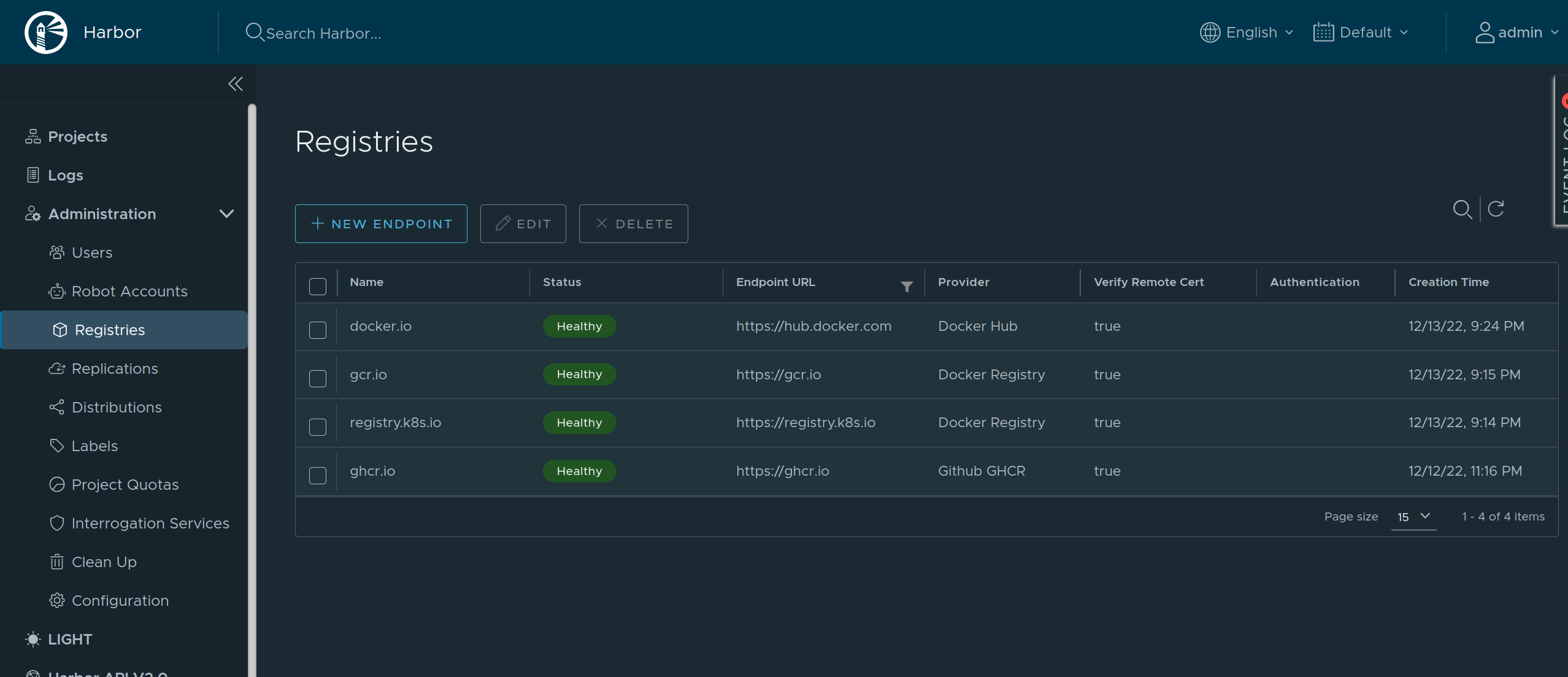
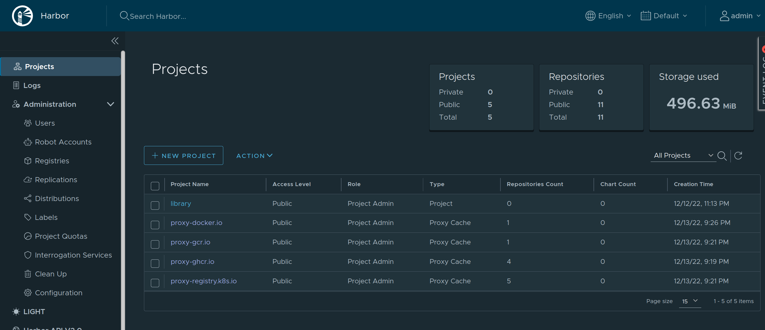
As Harbor puts a registry name in the pull image path, we need to set overridePath: true to prevent Talos and containerd from appending /v2 to the path.
machine:
registries:
mirrors:
docker.io:
endpoints:
- http://harbor/v2/proxy-docker.io
overridePath: true
ghcr.io:
endpoints:
- http://harbor/v2/proxy-ghcr.io
overridePath: true
gcr.io:
endpoints:
- http://harbor/v2/proxy-gcr.io
overridePath: true
registry.k8s.io:
endpoints:
- http://harbor/v2/proxy-registry.k8s.io
overridePath: true
The Harbor external endpoint (http://harbor in this example) can be configured with authentication or custom TLS:
machine:
registries:
config:
harbor:
auth:
username: admin
password: password
2.11 - Role-based access control (RBAC)
Talos v0.11 introduced initial support for role-based access control (RBAC). This guide will explain what that is and how to enable it without losing access to the cluster.
RBAC in Talos
Talos uses certificates to authorize users. The certificate subject’s organization field is used to encode user roles. There is a set of predefined roles that allow access to different API methods:
os:admingrants access to all methods;os:operatorgrants everythingos:readerrole does, plus additional methods: rebooting, shutting down, etcd backup, etcd alarm management, and so on;os:readergrants access to “safe” methods (for example, that includes the ability to list files, but does not include the ability to read files content);os:etcd:backupgrants access to/machine.MachineService/EtcdSnapshotmethod.
Roles in the current talosconfig can be checked with the following command:
$ talosctl config info
[...]
Roles: os:admin
[...]
RBAC is enabled by default in new clusters created with talosctl v0.11+ and disabled otherwise.
Enabling RBAC
First, both the Talos cluster and talosctl tool should be upgraded.
Then the talosctl config new command should be used to generate a new client configuration with the os:admin role.
Additional configurations and certificates for different roles can be generated by passing --roles flag:
talosctl config new --roles=os:reader reader
That command will create a new client configuration file reader with a new certificate with os:reader role.
After that, RBAC should be enabled in the machine configuration:
machine:
features:
rbac: true
2.12 - System Extensions
System extensions allow extending the Talos root filesystem, which enables a variety of features, such as including custom container runtimes, loading additional firmware, etc.
System extensions are only activated during the installation or upgrade of Talos Linux. With system extensions installed, the Talos root filesystem is still immutable and read-only.
Installing System Extensions
Note: the way to install system extensions in the
.machine.installsection of the machine configuration is now deprecated.
Starting with Talos v1.5.0, Talos supports generation of boot media with system extensions included, this removes the need to rebuild
the initramfs.xz on the machine itself during the installation or upgrade.
There are two kinds of boot assets that Talos can generate:
- initial boot assets (ISO, PXE, etc.) that are used to boot the machine
- disk images that have Talos pre-installed
installercontainer images that can be used to install or upgrade Talos on a machine (installation happens when booted from ISO or PXE)
Depending on the nature of the system extension (e.g. network device driver or containerd plugin), it may be necessary to include the extension in
both initial boot assets and disk images/installer, or just the installer.
The process of generating boot assets with extensions included is described in the boot assets guide.
Example: Booting from an ISO
Let’s assume NVIDIA extension is required on a bare metal machine which is going to be booted from an ISO.
As NVIDIA extension is not required for the initial boot and install step, it is sufficient to include the extension in the installer image only.
- Use a generic Talos ISO to boot the machine.
- Prepare a custom
installercontainer image with NVIDIA extension included, push the image to a registry. - Ensure that machine configuration field
.machine.install.imagepoints to the custominstallerimage. - Boot the machine using the ISO, apply the machine configuration.
- Talos pulls a custom installer image from the registry (containing NVIDIA extension), installs Talos on the machine, and reboots.
When it’s time to upgrade Talos, generate a custom installer container for a new version of Talos, push it to a registry, and perform upgrade
pointing to the custom installer image.
Example: Disk Image
Let’s assume NVIDIA extension is required on AWS VM.
- Prepare an AWS disk image with NVIDIA extension included.
- Upload the image to AWS, register it as an AMI.
- Use the AMI to launch a VM.
- Talos boots with NVIDIA extension included.
When it’s time to upgrade Talos, either repeat steps 1-4 to replace the VM with a new AMI, or
like in the previous example, generate a custom installer and use it to upgrade Talos in-place.
Authoring System Extensions
A Talos system extension is a container image with the specific folder structure.
System extensions can be built and managed using any tool that produces container images, e.g. docker build.
Sidero Labs maintains a repository of system extensions.
Resource Definitions
Use talosctl get extensions to get a list of system extensions:
$ talosctl get extensions
NODE NAMESPACE TYPE ID VERSION NAME VERSION
172.20.0.2 runtime ExtensionStatus 000.ghcr.io-talos-systems-gvisor-54b831d 1 gvisor 20220117.0-v1.0.0
172.20.0.2 runtime ExtensionStatus 001.ghcr.io-talos-systems-intel-ucode-54b831d 1 intel-ucode microcode-20210608-v1.0.0
Use YAML or JSON format to see additional details about the extension:
$ talosctl -n 172.20.0.2 get extensions 001.ghcr.io-talos-systems-intel-ucode-54b831d -o yaml
node: 172.20.0.2
metadata:
namespace: runtime
type: ExtensionStatuses.runtime.talos.dev
id: 001.ghcr.io-talos-systems-intel-ucode-54b831d
version: 1
owner: runtime.ExtensionStatusController
phase: running
created: 2022-02-10T18:25:04Z
updated: 2022-02-10T18:25:04Z
spec:
image: 001.ghcr.io-talos-systems-intel-ucode-54b831d.sqsh
metadata:
name: intel-ucode
version: microcode-20210608-v1.0.0
author: Spencer Smith
description: |
This system extension provides Intel microcode binaries.
compatibility:
talos:
version: '>= v1.0.0'
Example: gVisor
2.13 - Time Synchronization
Talos Linux itself does not require time to be synchronized across the cluster, but as Talos Linux and Kubernetes components issue certificates with expiration dates, it is recommended to have time synchronized across the cluster. Some workloads (e.g. Ceph) might require to be in sync across the machines in the cluster due to the design of the application.
Talos Linux tries to launch API even if the time is not sync, and if time jumps as a result of NTP sync, the API certificates will be rotated automatically.
Some components like kubelet and etcd wait for the time to be in sync before starting, as they don’t support graceful certificate rotation.
By default, Talos Linux uses time.cloudflare.com as the NTP server, but it can be overridden in the machine configuration, or provided via DHCP, kernel args, platform sources, etc.
Talos Linux implements SNTP protocol to sync time with the NTP server.
Observing Status
Current time sync status can be observed with:
$ talosctl get timestatus
NODE NAMESPACE TYPE ID VERSION SYNCED
172.20.0.2 runtime TimeStatus node 2 true
The list of servers Talos Linux is syncing with can be observed with:
$ talosctl get timeservers
NODE NAMESPACE TYPE ID VERSION TIMESERVERS
172.20.0.2 network TimeServerStatus timeservers 1 ["time.cloudflare.com"]
More detailed logs about the time sync process can be queried with:
$ talosctl logs controller-runtime | grep -i time.Sync
172.20.0.2: 2024-04-17T18:32:16.690Z DEBUG NTP response {"component": "controller-runtime", "controller": "time.SyncController", "clock_offset": "37.060204ms", "rtt": "3.044816ms", "leap": 0, "stratum": 3, "precision": "29ns", "root_delay": "70.617676ms", "root_dispersion": "259.399µs", "root_distance": "37.090645ms"}
172.20.0.2: 2024-04-17T18:32:16.690Z DEBUG sample stats {"component": "controller-runtime", "controller": "time.SyncController", "jitter": "150.196588ms", "poll_interval": "34m8s", "spike": false}
172.20.0.2: 2024-04-17T18:32:16.690Z DEBUG adjusting time (slew) by 37.060204ms via 162.159.200.1, state TIME_OK, status STA_PLL | STA_NANO {"component": "controller-runtime", "controller": "time.SyncController"}
172.20.0.2: 2024-04-17T18:32:16.690Z DEBUG adjtime state {"component": "controller-runtime", "controller": "time.SyncController", "constant": 7, "offset": "37.060203ms", "freq_offset": -1302069, "freq_offset_ppm": -19}
Using PTP Devices
When running in a VM on a hypervisor, instead of doing network time sync, Talos can sync the time to the hypervisor clock (if supported by the hypervisor).
To check if the PTP device is available:
$ talosctl ls /sys/class/ptp/
NODE NAME
172.20.0.2 .
172.20.0.2 ptp0
Make sure that the PTP device is provided by the hypervisor, as some PTP devices don’t provide accurate time value without proper setup:
talosctl read /sys/class/ptp/ptp0/clock_name
KVM virtual PTP
To enable PTP sync, set the machine.time.servers to the PTP device name (e.g. /dev/ptp0):
machine:
time:
servers:
- /dev/ptp0
After setting the PTP device, Talos will sync the time to the PTP device instead of using the NTP server:
172.20.0.2: 2024-04-17T19:11:48.817Z DEBUG adjusting time (slew) by 32.223689ms via /dev/ptp0, state TIME_OK, status STA_PLL | STA_NANO {"component": "controller-runtime", "controller": "time.SyncController"}
Additional Configuration
Talos NTP sync can be disabled with the following machine configuration patch:
machine:
time:
disabled: true
When time sync is disabled, Talos assumes that time is always in sync.
Time sync can be also configured on best-effort basis, where Talos will try to sync time for the specified period of time, but if it fails to do so, time will be configured to be in sync when the period expires:
machine:
time:
bootTimeout: 2m
3 - How Tos
3.1 - How to enable workers on your control plane nodes
By default, Talos Linux taints control plane nodes so that workloads are not schedulable on them.
In order to allow workloads to run on the control plane nodes (useful for single node clusters, or non-production clusters), follow the procedure below.
Modify the MachineConfig for the controlplane nodes to add allowSchedulingOnControlPlanes: true:
cluster:
allowSchedulingOnControlPlanes: true
This may be done via editing the controlplane.yaml file before it is applied to the control plane nodes, by editing the machine config, or by patching the machine config.
3.2 - How to manage PKI and certificate lifetimes with Talos Linux
Talos Linux automatically manages and rotates all server side certificates for etcd, Kubernetes, and the Talos API. Note however that the kubelet needs to be restarted at least once a year in order for the certificates to be rotated. Any upgrade/reboot of the node will suffice for this effect.
You can check the Kubernetes certificates with the command talosctl get KubernetesDynamicCerts -o yaml on the controlplane.
Client certificates (talosconfig and kubeconfig) are the user’s responsibility.
Each time you download the kubeconfig file from a Talos Linux cluster, the client certificate is regenerated giving you a kubeconfig which is valid for a year.
The talosconfig file should be renewed at least once a year, using the talosctl config new command, as shown below, or by one of the other methods.
Generating New Client Configuration
Using Controlplane Node
If you have a valid (not expired) talosconfig with os:admin role,
a new client configuration file can be generated with talosctl config new against
any controlplane node:
talosctl -n CP1 config new talosconfig-reader --roles os:reader --crt-ttl 24h
A specific role and certificate lifetime can be specified.
From Secrets Bundle
If a secrets bundle (secrets.yaml from talosctl gen secrets) was saved while
generating machine configuration:
talosctl gen config --with-secrets secrets.yaml --output-types talosconfig -o talosconfig <cluster-name> https://<cluster-endpoint>
Note:
<cluster-name>and<cluster-endpoint>arguments don’t matter, as they are not used fortalosconfig.
From Control Plane Machine Configuration
In order to create a new key pair for client configuration, you will need the root Talos API CA.
The base64 encoded CA can be found in the control plane node’s configuration file.
Save the CA public key, and CA private key as ca.crt, and ca.key respectively:
yq eval .machine.ca.crt controlplane.yaml | base64 -d > ca.crt
yq eval .machine.ca.key controlplane.yaml | base64 -d > ca.key
Now, run the following commands to generate a certificate:
talosctl gen key --name admin
talosctl gen csr --key admin.key --ip 127.0.0.1
talosctl gen crt --ca ca --csr admin.csr --name admin
Put the base64-encoded files to the respective location to the talosconfig:
context: mycluster
contexts:
mycluster:
endpoints:
- CP1
- CP2
ca: <base64-encoded ca.crt>
crt: <base64-encoded admin.crt>
key: <base64-encoded admin.key>
3.3 - How to scale down a Talos cluster
To remove nodes from a Talos Linux cluster:
talosctl -n <IP.of.node.to.remove> resetkubectl delete node <nodename>
The command talosctl reset will cordon and drain the node, leaving etcd if required, and then erase its disks and power down the system.
This command will also remove the node from registration with the discovery service, so it will no longer show up in talosctl get members.
It is still necessary to remove the node from Kubernetes, as noted above.
3.4 - How to scale up a Talos cluster
To add more nodes to a Talos Linux cluster, follow the same procedure as when initially creating the cluster:
- boot the new machines to install Talos Linux
- apply the
worker.yamlorcontrolplane.yamlconfiguration files to the new machines
You need the controlplane.yaml and worker.yaml that were created when you initially deployed your cluster.
These contain the certificates that enable new machines to join.
Once you have the IP address, you can then apply the correct configuration for each machine you are adding, either worker or controlplane.
talosctl apply-config --insecure \
--nodes [NODE IP] \
--file controlplane.yaml
The insecure flag is necessary because the PKI infrastructure has not yet been made available to the node.
You do not need to bootstrap the new node. Regardless of whether you are adding a control plane or worker node, it will now join the cluster in its role.
4 - Network
4.1 - Corporate Proxies
Appending the Certificate Authority of MITM Proxies
Put into each machine the PEM encoded certificate:
machine:
...
files:
- content: |
-----BEGIN CERTIFICATE-----
...
-----END CERTIFICATE-----
permissions: 0644
path: /etc/ssl/certs/ca-certificates
op: append
Configuring a Machine to Use the Proxy
To make use of a proxy:
machine:
env:
http_proxy: <http proxy>
https_proxy: <https proxy>
no_proxy: <no proxy>
Additionally, configure the DNS nameservers, and NTP servers:
machine:
env:
...
time:
servers:
- <server 1>
- <server ...>
- <server n>
...
network:
nameservers:
- <ip 1>
- <ip ...>
- <ip n>
If a proxy is required before Talos machine configuration is applied, use kernel command line arguments:
talos.environment=http_proxy=<http-proxy> talos.environment=https_proxy=<https-proxy>
4.2 - Host DNS
Talos Linux starting with 1.7.0 provides a caching DNS resolver for host workloads (including host networking pods). Host DNS resolver is enabled by default for clusters created with Talos 1.7, and it can be enabled manually on upgrade.
Enabling Host DNS
Use the following machine configuration patch to enable host DNS resolver:
machine:
features:
hostDNS:
enabled: true
Host DNS can be disabled by setting enabled: false as well.
Operations
When enabled, Talos Linux starts a DNS caching server on the host, listening on address 127.0.0.53:53 (both TCP and UDP protocols).
The host /etc/resolv.conf file is rewritten to point to the host DNS server:
$ talosctl read /etc/resolv.conf
nameserver 127.0.0.53
All host-based workloads will use the host DNS server for name resolution. Host DNS server forwards requests to the upstream DNS servers, which are either acquired automatically (DHCP, platform sources, kernel args), or specified in the machine configuration.
The upstream DNS servers can be observed with:
$ talosctl get resolvers
NODE NAMESPACE TYPE ID VERSION RESOLVERS
172.20.0.2 network ResolverStatus resolvers 2 ["8.8.8.8","1.1.1.1"]
Logs of the host DNS resolver can be queried with:
talosctl logs dns-resolve-cache
Upstream server status can be observed with:
$ talosctl get dnsupstream
NODE NAMESPACE TYPE ID VERSION HEALTHY ADDRESS
172.20.0.2 network DNSUpstream 1.1.1.1 1 true 1.1.1.1:53
172.20.0.2 network DNSUpstream 8.8.8.8 1 true 8.8.8.8:53
Forwarding kube-dns to Host DNS
When host DNS is enabled, by default, kube-dns service (CoreDNS in Kubernetes) uses upstream DNS servers to resolve external names.
But Talos allows forwarding kube-dns to the host DNS resolver, so that the cache is shared between the host and kube-dns:
machine:
features:
hostDNS:
enabled: true
forwardKubeDNSToHost: true
This configuration should be applied to all nodes in the cluster, if enabled after cluster creation, restart coredns pods in Kubernetes to pick up changes.
When forwardKubeDNSToHost is enabled, Talos Linux allocates 9th IP address in the serviceSubnet range for host DNS server, and kube-dns service is configured to use this IP address as the upstream DNS server:
$ kubectl get services -n kube-system host-dns
NAME TYPE CLUSTER-IP EXTERNAL-IP PORT(S) AGE
host-dns ClusterIP 10.96.0.9 <none> 53/UDP,53/TCP 27s
$ talosctl read /system/resolved/resolv.conf
nameserver 10.96.0.9
With this configuration, kube-dns service forwards all DNS requests to the host DNS server, and the cache is shared between the host and kube-dns.
Resolving Talos Cluster Member Names
Host DNS can be configured to resolve Talos cluster member names to IP addresses, so that the host can communicate with the cluster members by name. Sometimes machine hostnames are already resolvable by the upstream DNS, but this might not always be the case.
Enabling the feature:
machine:
features:
hostDNS:
enabled: true
resolveMemberNames: true
When enabled, Talos Linux uses discovery data to resolve Talos cluster member names to IP addresses:
$ talosctl get members
NODE NAMESPACE TYPE ID VERSION HOSTNAME MACHINE TYPE OS ADDRESSES
172.20.0.2 cluster Member talos-default-controlplane-1 1 talos-default-controlplane-1 controlplane Talos (v1.7.6) ["172.20.0.2"]
172.20.0.2 cluster Member talos-default-worker-1 1 talos-default-worker-1 worker Talos (v1.7.6) ["172.20.0.3"]
With the example output above, talos-default-worker-1 name will resolve to 127.0.0.3.
Example usage:
talosctl -n talos-default-worker-1 version
When combined with forwardKubeDNSToHost, kube-dns service will also resolve Talos cluster member names to IP addresses.
4.3 - Ingress Firewall
Talos Linux Ingress Firewall is a simple and effective way to limit network access to the services running on the host, which includes both Talos standard
services (e.g. apid and kubelet), and any additional workloads that may be running on the host.
Talos Linux Ingress Firewall doesn’t affect the traffic between the Kubernetes pods/services, please use CNI Network Policies for that.
Configuration
Ingress rules are configured as extra documents NetworkDefaultActionConfig and NetworkRuleConfig in the Talos machine configuration:
apiVersion: v1alpha1
kind: NetworkDefaultActionConfig
ingress: block
---
apiVersion: v1alpha1
kind: NetworkRuleConfig
name: kubelet-ingress
portSelector:
ports:
- 10250
protocol: tcp
ingress:
- subnet: 172.20.0.0/24
except: 172.20.0.1/32
The first document configures the default action for ingress traffic, which can be either accept or block, with the default being accept.
If the default action is set to accept, then all ingress traffic will be allowed, unless there is a matching rule that blocks it.
If the default action is set to block, then all ingress traffic will be blocked, unless there is a matching rule that allows it.
With either accept or block, traffic is always allowed on the following network interfaces:
losiderolinkkubespan
In block mode:
- ICMP and ICMPv6 traffic is also allowed with a rate limit of 5 packets per second
- traffic between Kubernetes pod/service subnets is allowed (for native routing CNIs)
The second document defines an ingress rule for a set of ports and protocols on the host.
The NetworkRuleConfig might be repeated many times to define multiple rules, but each document must have a unique name.
The ports field accepts either a single port or a port range:
portSelector:
ports:
- 10250
- 10260
- 10300-10400
The protocol might be either tcp or udp.
The ingress specifies the list of subnets that are allowed to access the host services, with the optional except field to exclude a set of addresses from the subnet.
Note: incorrect configuration of the ingress firewall might result in the host becoming inaccessible over Talos API. It is recommended that the configuration be applied in
--mode=tryto ensure it is reverted in case of a mistake.
Recommended Rules
The following rules improve the security of the cluster and cover only standard Talos services. If there are additional services running with host networking in the cluster, they should be covered by additional rules.
In block mode, the ingress firewall will also block encapsulated traffic (e.g. VXLAN) between the nodes, which needs to be explicitly allowed for the Kubernetes
networking to function properly.
Please refer to the documentation of the CNI in use for the specific ports required.
Some default configurations are listed below:
- Flannel, Calico:
vxlanUDP port 4789 - Cilium:
vxlanUDP port 8472
In the examples we assume the following template variables to describe the cluster:
$CLUSTER_SUBNET, e.g.172.20.0.0/24- the subnet which covers all machines in the cluster$CP1,$CP2,$CP3- the IP addresses of the controlplane nodes$VXLAN_PORT- the UDP port used by the CNI for encapsulated traffic
Controlplane
In this example Ingress policy:
apidand Kubernetes API are wide openkubeletandtrustdAPI are only accessible within the clusteretcdAPI is limited to controlplane nodes
apiVersion: v1alpha1
kind: NetworkDefaultActionConfig
ingress: block
---
apiVersion: v1alpha1
kind: NetworkRuleConfig
name: kubelet-ingress
portSelector:
ports:
- 10250
protocol: tcp
ingress:
- subnet: $CLUSTER_SUBNET
---
apiVersion: v1alpha1
kind: NetworkRuleConfig
name: apid-ingress
portSelector:
ports:
- 50000
protocol: tcp
ingress:
- subnet: 0.0.0.0/0
- subnet: ::/0
---
apiVersion: v1alpha1
kind: NetworkRuleConfig
name: trustd-ingress
portSelector:
ports:
- 50001
protocol: tcp
ingress:
- subnet: $CLUSTER_SUBNET
---
apiVersion: v1alpha1
kind: NetworkRuleConfig
name: kubernetes-api-ingress
portSelector:
ports:
- 6443
protocol: tcp
ingress:
- subnet: 0.0.0.0/0
- subnet: ::/0
---
apiVersion: v1alpha1
kind: NetworkRuleConfig
name: etcd-ingress
portSelector:
ports:
- 2379-2380
protocol: tcp
ingress:
- subnet: $CP1/32
- subnet: $CP2/32
- subnet: $CP3/32
---
apiVersion: v1alpha1
kind: NetworkRuleConfig
name: cni-vxlan
portSelector:
ports:
- $VXLAN_PORT
protocol: udp
ingress:
- subnet: $CLUSTER_SUBNET
Worker
kubeletandapidAPI are only accessible within the cluster
apiVersion: v1alpha1
kind: NetworkDefaultActionConfig
ingress: block
---
apiVersion: v1alpha1
kind: NetworkRuleConfig
name: kubelet-ingress
portSelector:
ports:
- 10250
protocol: tcp
ingress:
- subnet: $CLUSTER_SUBNET
---
apiVersion: v1alpha1
kind: NetworkRuleConfig
name: apid-ingress
portSelector:
ports:
- 50000
protocol: tcp
ingress:
- subnet: $CLUSTER_SUBNET
---
apiVersion: v1alpha1
kind: NetworkRuleConfig
name: cni-vxlan
portSelector:
ports:
- $VXLAN_PORT
protocol: udp
ingress:
- subnet: $CLUSTER_SUBNET
Learn More
Talos Linux Ingress Firewall uses nftables to perform the filtering.
With the default action set to accept, the following rules are applied (example):
table inet talos {
chain ingress {
type filter hook input priority filter; policy accept;
iifname { "lo", "siderolink", "kubespan" } accept
ip saddr != { 172.20.0.0/24 } tcp dport { 10250 } drop
meta nfproto ipv6 tcp dport { 10250 } drop
}
}
With the default action set to block, the following rules are applied (example):
table inet talos {
chain ingress {
type filter hook input priority filter; policy drop;
iifname { "lo", "siderolink", "kubespan" } accept
ct state { established, related } accept
ct state invalid drop
meta l4proto icmp limit rate 5/second accept
meta l4proto ipv6-icmp limit rate 5/second accept
ip saddr { 172.20.0.0/24 } tcp dport { 10250 } accept
meta nfproto ipv4 tcp dport { 50000 } accept
meta nfproto ipv6 tcp dport { 50000 } accept
}
}
The running nftable configuration can be inspected with talosctl get nftableschain -o yaml.
The Ingress Firewall documents can be extracted from the machine config with the following command:
talosctl read /system/state/config.yaml | yq 'select(.kind == "NetworkDefaultActionConfig"),select(.kind == "NetworkRuleConfig" )'
4.4 - KubeSpan
KubeSpan is a feature of Talos that automates the setup and maintenance of a full mesh WireGuard network for your cluster, giving you the ability to operate hybrid Kubernetes clusters that can span the edge, datacenter, and cloud. Management of keys and discovery of peers can be completely automated, making it simple and easy to create hybrid clusters.
KubeSpan consists of client code in Talos Linux, as well as a discovery service that enables clients to securely find each other. Sidero Labs operates a free Discovery Service, but the discovery service may, with a commercial license, be operated by your organization and can be downloaded here.
Video Walkthrough
To see a live demo of KubeSpan, see one the videos below:
Network Requirements
KubeSpan uses UDP port 51820 to carry all KubeSpan encrypted traffic. Because UDP traversal of firewalls is often lenient, and the Discovery Service communicates the apparent IP address of all peers to all other peers, KubeSpan will often work automatically, even when each nodes is behind their own firewall. However, when both ends of a KubeSpan connection are behind firewalls, it is possible the connection may not be established correctly - it depends on each end sending out packets in a limited time window.
Thus best practice is to ensure that one end of all possible node-node communication allows UDP port 51820, inbound.
For example, if control plane nodes are running in a corporate data center, behind firewalls, KubeSpan connectivity will work correctly so long as worker nodes on the public Internet can receive packets on UDP port 51820.
(Note the workers will also need to receive TCP port 50000 for initial configuration via talosctl).
An alternative topology would be to run control plane nodes in a public cloud, and allow inbound UDP port 51820 to the control plane nodes. Workers could be behind firewalls, and KubeSpan connectivity will be established. Note that if workers are in different locations, behind different firewalls, the KubeSpan connectivity between workers should be correctly established, but may require opening the KubeSpan UDP port on the local firewall also.
Caveats
Kubernetes API Endpoint Limitations
When the K8s endpoint is an IP address that is not part of Kubespan, but is an address that is forwarded on to the Kubespan address of a control plane node, without changing the source address, then worker nodes will fail to join the cluster. In such a case, the control plane node has no way to determine whether the packet arrived on the private Kubespan address, or the public IP address. If the source of the packet was a Kubespan member, the reply will be Kubespan encapsulated, and thus not translated to the public IP, and so the control plane will reply to the session with the wrong address.
This situation is seen, for example, when the Kubernetes API endpoint is the public IP of a VM in GCP or Azure for a single node control plane. The control plane will receive packets on the public IP, but will reply from it’s KubeSpan address. The workaround is to create a load balancer to terminate the Kubernetes API endpoint.
Digital Ocean Limitations
Digital Ocean assigns an “Anchor IP” address to each droplet. Talos Linux correctly identifies this as a link-local address, and configures KubeSpan correctly, but this address will often be selected by Flannel or other CNIs as a node’s private IP. Because this address is not routable, nor advertised via KubeSpan, it will break pod-pod communication between nodes. This can be worked-around by assigning a non-Anchor private IP:
kubectl annotate node do-worker flannel.alpha.coreos.com/public-ip-overwrite=10.116.X.X
Then restarting flannel:
kubectl delete pods -n kube-system -l k8s-app=flannel
Enabling
Creating a New Cluster
To enable KubeSpan for a new cluster, we can use the --with-kubespan flag in talosctl gen config.
This will enable peer discovery and KubeSpan.
machine:
network:
kubespan:
enabled: true # Enable the KubeSpan feature.
cluster:
discovery:
enabled: true
# Configure registries used for cluster member discovery.
registries:
kubernetes: # Kubernetes registry is problematic with KubeSpan, if the control plane endpoint is routeable itself via KubeSpan.
disabled: true
service: {}
The default discovery service is an external service hosted by Sidero Labs at
https://discovery.talos.dev/. Contact Sidero Labs if you need to run this service privately.
Enabling for an Existing Cluster
In order to enable KubeSpan on an existing cluster, enable kubespan and discovery settings in the machine config for each machine in the cluster (discovery is enabled by default):
machine:
network:
kubespan:
enabled: true
cluster:
discovery:
enabled: true
Configuration
KubeSpan will automatically discover all cluster members, exchange Wireguard public keys and establish a full mesh network.
There are configuration options available which are not usually required:
machine:
network:
kubespan:
enabled: false
advertiseKubernetesNetworks: false
allowDownPeerBypass: false
mtu: 1420
filters:
endpoints:
- 0.0.0.0/0
- ::/0
The setting advertiseKubernetesNetworks controls whether the node will advertise Kubernetes service and pod networks to other nodes in the cluster over KubeSpan.
It defaults to being disabled, which means KubeSpan only controls the node-to-node traffic, while pod-to-pod traffic is routed and encapsulated by CNI.
This setting should not be enabled with Calico and Cilium CNI plugins, as they do their own pod IP allocation which is not visible to KubeSpan.
The setting allowDownPeerBypass controls whether the node will allow traffic to bypass WireGuard if the destination is not connected over KubeSpan.
If enabled, there is a risk that traffic will be routed unencrypted if the destination is not connected over KubeSpan, but it allows a workaround
for the case where a node is not connected to the KubeSpan network, but still needs to access the cluster.
The mtu setting configures the Wireguard MTU, which defaults to 1420.
This default value of 1420 is safe to use when the underlying network MTU is 1500, but if the underlying network MTU is smaller, the KubeSpanMTU should be adjusted accordingly:
KubeSpanMTU = UnderlyingMTU - 80.
The filters setting allows hiding some endpoints from being advertised over KubeSpan.
This is useful when some endpoints are known to be unreachable between the nodes, so that KubeSpan doesn’t try to establish a connection to them.
Another use-case is hiding some endpoints if nodes can connect on multiple networks, and some of the networks are more preferable than others.
Resource Definitions
KubeSpanIdentities
A node’s WireGuard identities can be obtained with:
$ talosctl get kubespanidentities -o yaml
...
spec:
address: fd83:b1f7:fcb5:2802:8c13:71ff:feaf:7c94/128
subnet: fd83:b1f7:fcb5:2802::/64
privateKey: gNoasoKOJzl+/B+uXhvsBVxv81OcVLrlcmQ5jQwZO08=
publicKey: NzW8oeIH5rJyY5lefD9WRoHWWRr/Q6DwsDjMX+xKjT4=
Talos automatically configures unique IPv6 address for each node in the cluster-specific IPv6 ULA prefix.
The Wireguard private key is generated and never leaves the node, while the public key is published through the cluster discovery.
KubeSpanIdentity is persisted across reboots and upgrades in STATE partition in the file kubespan-identity.yaml.
KubeSpanPeerSpecs
A node’s WireGuard peers can be obtained with:
$ talosctl get kubespanpeerspecs
ID VERSION LABEL ENDPOINTS
06D9QQOydzKrOL7oeLiqHy9OWE8KtmJzZII2A5/FLFI= 2 talos-default-controlplane-2 ["172.20.0.3:51820"]
THtfKtfNnzJs1nMQKs5IXqK0DFXmM//0WMY+NnaZrhU= 2 talos-default-controlplane-3 ["172.20.0.4:51820"]
nVHu7l13uZyk0AaI1WuzL2/48iG8af4WRv+LWmAax1M= 2 talos-default-worker-2 ["172.20.0.6:51820"]
zXP0QeqRo+CBgDH1uOBiQ8tA+AKEQP9hWkqmkE/oDlc= 2 talos-default-worker-1 ["172.20.0.5:51820"]
The peer ID is the Wireguard public key.
KubeSpanPeerSpecs are built from the cluster discovery data.
KubeSpanPeerStatuses
The status of a node’s WireGuard peers can be obtained with:
$ talosctl get kubespanpeerstatuses
ID VERSION LABEL ENDPOINT STATE RX TX
06D9QQOydzKrOL7oeLiqHy9OWE8KtmJzZII2A5/FLFI= 63 talos-default-controlplane-2 172.20.0.3:51820 up 15043220 17869488
THtfKtfNnzJs1nMQKs5IXqK0DFXmM//0WMY+NnaZrhU= 62 talos-default-controlplane-3 172.20.0.4:51820 up 14573208 18157680
nVHu7l13uZyk0AaI1WuzL2/48iG8af4WRv+LWmAax1M= 60 talos-default-worker-2 172.20.0.6:51820 up 130072 46888
zXP0QeqRo+CBgDH1uOBiQ8tA+AKEQP9hWkqmkE/oDlc= 60 talos-default-worker-1 172.20.0.5:51820 up 130044 46556
KubeSpan peer status includes following information:
- the actual endpoint used for peer communication
- link state:
unknown: the endpoint was just changed, link state is not known yetup: there is a recent handshake from the peerdown: there is no handshake from the peer
- number of bytes sent/received over the Wireguard link with the peer
If the connection state goes down, Talos will be cycling through the available endpoints until it finds the one which works.
Peer status information is updated every 30 seconds.
KubeSpanEndpoints
A node’s WireGuard endpoints (peer addresses) can be obtained with:
$ talosctl get kubespanendpoints
ID VERSION ENDPOINT AFFILIATE ID
06D9QQOydzKrOL7oeLiqHy9OWE8KtmJzZII2A5/FLFI= 1 172.20.0.3:51820 2VfX3nu67ZtZPl57IdJrU87BMjVWkSBJiL9ulP9TCnF
THtfKtfNnzJs1nMQKs5IXqK0DFXmM//0WMY+NnaZrhU= 1 172.20.0.4:51820 b3DebkPaCRLTLLWaeRF1ejGaR0lK3m79jRJcPn0mfA6C
nVHu7l13uZyk0AaI1WuzL2/48iG8af4WRv+LWmAax1M= 1 172.20.0.6:51820 NVtfu1bT1QjhNq5xJFUZl8f8I8LOCnnpGrZfPpdN9WlB
zXP0QeqRo+CBgDH1uOBiQ8tA+AKEQP9hWkqmkE/oDlc= 1 172.20.0.5:51820 6EVq8RHIne03LeZiJ60WsJcoQOtttw1ejvTS6SOBzhUA
The endpoint ID is the base64 encoded WireGuard public key.
The observed endpoints are submitted back to the discovery service (if enabled) so that other peers can try additional endpoints to establish the connection.
4.5 - Network Device Selector
Configuring Network Device Using Device Selector
deviceSelector is an alternative method of configuring a network device:
machine:
...
network:
interfaces:
- deviceSelector:
driver: virtio
hardwareAddr: "00:00:*"
address: 192.168.88.21
Selector has the following traits:
- qualifiers match a device by reading the hardware information in
/sys/class/net/... - qualifiers are applied using logical
AND machine.network.interfaces.deviceConfigoption is mutually exclusive withmachine.network.interfaces.interface- if the selector matches multiple devices, the controller will apply config to all of them
The available hardware information used in the selector can be observed in the LinkStatus resource (works in maintenance mode):
# talosctl get links eth0 -o yaml
spec:
...
hardwareAddr: 4e:95:8e:8f:e4:47
busPath: 0000:06:00.0
driver: alx
pciID: 1969:E0B1
The following qualifiers are available:
driver- matches a device by its driver namehardwareAddr- matches a device by its hardware addressbusPath- matches a device by its PCI bus pathpciID- matches a device by its PCI vendor and device IDphysical- matches only physical devices (vs. virtual devices, e.g. bonds and VLANs)
All qualifiers except for physical support wildcard matching using * character.
Using Device Selector for Bonding
Device selectors can be used to configure bonded interfaces:
machine:
...
network:
interfaces:
- interface: bond0
bond:
mode: balance-rr
deviceSelectors:
- hardwareAddr: '00:50:56:8e:8f:e4'
- hardwareAddr: '00:50:57:9c:2c:2d'
In this example, the bond0 interface will be created and bonded using two devices with the specified hardware addresses.
4.6 - Predictable Interface Names
Starting with version Talos 1.5, network interfaces are renamed to predictable names
same way as systemd does that in other Linux distributions.
The naming schema enx78e7d1ea46da (based on MAC addresses) is enabled by default, the order of interface naming decisions is:
- firmware/BIOS provided index numbers for on-board devices (example:
eno1) - firmware/BIOS provided PCI Express hotplug slot index numbers (example:
ens1) - physical/geographical location of the connector of the hardware (example:
enp2s0) - interfaces’s MAC address (example:
enx78e7d1ea46da)
The predictable network interface names features can be disabled by specifying net.ifnames=0 in the kernel command line.
Note: Talos automatically adds the
net.ifnames=0kernel argument when upgrading from Talos versions before 1.5, so upgrades to 1.5 don’t require any manual intervention.
“Cloud” platforms, like AWS, still use old eth0 naming scheme as Talos automatically adds net.ifnames=0 to the kernel command line.
Single Network Interface
When running Talos on a machine with a single network interface, predictable interface names might be confusing, as it might come up as enxSOMETHING which is hard to address.
There are two ways to solve this:
disable the feature by supplying
net.ifnames=0to the initial boot of Talos, Talos will persistnet.ifnames=0over installs/upgrades.use device selectors:
machine: network: interfaces: - deviceSelector: busPath: "0*" # should select any hardware network device, if you have just one, it will be selected # any configuration can follow, e.g: addresses: [10.3.4.5/24]
4.7 - SideroLink
SideroLink provides a secure point-to-point management overlay network for Talos clusters. Each Talos machine configured to use SideroLink will establish a secure Wireguard connection to the SideroLink API server. SideroLink provides overlay network using ULA IPv6 addresses allowing to manage Talos Linux machines even if direct access to machine IP addresses is not possible. SideroLink is a foundation building block of Sidero Omni.
Configuration
SideroLink is configured by providing the SideroLink API server address, either via kernel command line argument siderolink.api or as a config document.
SideroLink API URL: https://siderolink.api/?jointoken=token&grpc_tunnel=true.
If URL scheme is grpc://, the connection will be established without TLS, otherwise, the connection will be established with TLS.
If specified, join token token will be sent to the SideroLink server.
If grpc_tunnel is set to true, the Wireguard traffic will be tunneled over the same SideroLink API gRPC connection instead of using plain UDP.
Connection Flow
- Talos Linux creates an ephemeral Wireguard key.
- Talos Linux establishes a gRPC connection to the SideroLink API server, sends its own Wireguard public key, join token and other connection settings.
- If the join token is valid, the SideroLink API server sends back the Wireguard public key of the SideroLink API server, and two overlay IPv6 addresses: machine address and SideroLink server address.
- Talos Linux configured Wireguard interface with the received settings.
- Talos Linux monitors status of the Wireguard connection and re-establishes the connection if needed.
Operations with SideroLink
When SideroLink is configured, Talos maintenance mode API listens only on the SideroLink network. Maintenance mode API over SideroLink allows operations which are not generally available over the public network: getting Talos version, getting sensitive resources, etc.
Talos Linux always provides Talos API over SideroLink, and automatically allows access over SideroLink even if the Ingress Firewall is enabled. Wireguard connections should be still allowed by the Ingress Firewall.
SideroLink only allows point-to-point connections between Talos machines and the SideroLink management server, two Talos machines cannot communicate directly over SideroLink.
4.8 - Virtual (shared) IP
One of the pain points when building a high-availability controlplane is giving clients a single IP or URL at which they can reach any of the controlplane nodes. The most common approaches - reverse proxy, load balancer, BGP, and DNS - all require external resources, and add complexity in setting up Kubernetes.
To simplify cluster creation, Talos Linux supports a “Virtual” IP (VIP) address to access the Kubernetes API server, providing high availability with no other resources required.
What happens is that the controlplane machines vie for control of the shared IP address using etcd elections. There can be only one owner of the IP address at any given time. If that owner disappears or becomes non-responsive, another owner will be chosen, and it will take up the IP address.
Requirements
The controlplane nodes must share a layer 2 network, and the virtual IP must be assigned from that shared network subnet.
In practical terms, this means that they are all connected via a switch, with no router in between them.
Note that the virtual IP election depends on etcd being up, as Talos uses etcd for elections and leadership (control) of the IP address.
The virtual IP is not restricted by ports - you can access any port that the control plane nodes are listening on, on that IP address. Thus it is possible to access the Talos API over the VIP, but it is not recommended, as you cannot access the VIP when etcd is down - and then you could not access the Talos API to recover etcd.
Video Walkthrough
To see a live demo of this writeup, see the video below:
Choose your Shared IP
The Virtual IP should be a reserved, unused IP address in the same subnet as your controlplane nodes. It should not be assigned or assignable by your DHCP server.
For our example, we will assume that the controlplane nodes have the following IP addresses:
192.168.0.10192.168.0.11192.168.0.12
We then choose our shared IP to be:
192.168.0.15
Configure your Talos Machines
The shared IP setting is only valid for controlplane nodes.
For the example above, each of the controlplane nodes should have the following Machine Config snippet:
machine:
network:
interfaces:
- interface: eth0
dhcp: true
vip:
ip: 192.168.0.15
Virtual IP’s can also be configured on a VLAN interface.
machine:
network:
interfaces:
- interface: eth0
dhcp: true
vip:
ip: 192.168.0.15
vlans:
- vlanId: 100
dhcp: true
vip:
ip: 192.168.1.15
For your own environment, the interface and the DHCP setting may differ, or you may
use static addressing (adresses) instead of DHCP.
When using predictable interface names, the interface name might not be eth0.
If the machine has a single network interface, it can be selected using a dummy device selector:
machine:
network:
interfaces:
- deviceSelector:
physical: true # should select any hardware network device, if you have just one, it will be selected
dhcp: true
vip:
ip: 192.168.0.15
Caveats
Since VIP functionality relies on etcd for elections, the shared IP will not come
alive until after you have bootstrapped Kubernetes.
Don’t use the VIP as the endpoint in the talosconfig, as the VIP is bound to etcd and kube-apiserver health, and you will not be able to recover from a failure of either of those components using Talos API.
4.9 - Wireguard Network
Configuring Wireguard Network
Quick Start
The quickest way to try out Wireguard is to use talosctl cluster create command:
talosctl cluster create --wireguard-cidr 10.1.0.0/24
It will automatically generate Wireguard network configuration for each node with the following network topology:
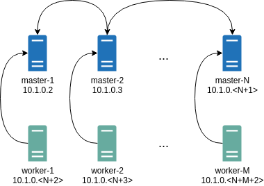
Where all controlplane nodes will be used as Wireguard servers which listen on port 51111.
All controlplanes and workers will connect to all controlplanes.
It also sets PersistentKeepalive to 5 seconds to establish controlplanes to workers connection.
After the cluster is deployed it should be possible to verify Wireguard network connectivity.
It is possible to deploy a container with hostNetwork enabled, then do kubectl exec <container> /bin/bash and either do:
ping 10.1.0.2
Or install wireguard-tools package and run:
wg show
Wireguard show should output something like this:
interface: wg0
public key: OMhgEvNIaEN7zeCLijRh4c+0Hwh3erjknzdyvVlrkGM=
private key: (hidden)
listening port: 47946
peer: 1EsxUygZo8/URWs18tqB5FW2cLVlaTA+lUisKIf8nh4=
endpoint: 10.5.0.2:51111
allowed ips: 10.1.0.0/24
latest handshake: 1 minute, 55 seconds ago
transfer: 3.17 KiB received, 3.55 KiB sent
persistent keepalive: every 5 seconds
It is also possible to use generated configuration as a reference by pulling generated config files using:
talosctl read -n 10.5.0.2 /system/state/config.yaml > controlplane.yaml
talosctl read -n 10.5.0.3 /system/state/config.yaml > worker.yaml
Manual Configuration
All Wireguard configuration can be done by changing Talos machine config files. As an example we will use this official Wireguard quick start tutorial.
Key Generation
This part is exactly the same:
wg genkey | tee privatekey | wg pubkey > publickey
Setting up Device
Inline comments show relations between configs and wg quickstart tutorial commands:
...
network:
interfaces:
...
# ip link add dev wg0 type wireguard
- interface: wg0
mtu: 1500
# ip address add dev wg0 192.168.2.1/24
addresses:
- 192.168.2.1/24
# wg set wg0 listen-port 51820 private-key /path/to/private-key peer ABCDEF... allowed-ips 192.168.88.0/24 endpoint 209.202.254.14:8172
wireguard:
privateKey: <privatekey file contents>
listenPort: 51820
peers:
allowedIPs:
- 192.168.88.0/24
endpoint: 209.202.254.14.8172
publicKey: ABCDEF...
...
When networkd gets this configuration it will create the device, configure it and will bring it up (equivalent to ip link set up dev wg0).
All supported config parameters are described in the Machine Config Reference.
5 - Discovery Service
Talos Linux includes node-discovery capabilities that depend on a discovery registry. This allows you to see the members of your cluster, and the associated IP addresses of the nodes.
talosctl get members
NODE NAMESPACE TYPE ID VERSION HOSTNAME MACHINE TYPE OS ADDRESSES
10.5.0.2 cluster Member talos-default-controlplane-1 1 talos-default-controlplane-1 controlplane Talos (v1.2.3) ["10.5.0.2"]
10.5.0.2 cluster Member talos-default-worker-1 1 talos-default-worker-1 worker Talos (v1.2.3) ["10.5.0.3"]
There are currently two supported discovery services: a Kubernetes registry (which stores data in the cluster’s etcd service) and an external registry service. Sidero Labs runs a public external registry service, which is enabled by default. The Kubernetes registry service is disabled by default. The advantage of the external registry service is that it is not dependent on etcd, and thus can inform you of cluster membership even when Kubernetes is down.
Video Walkthrough
To see a live demo of Cluster Discovery, see the video below:
Registries
Peers are aggregated from enabled registries.
By default, Talos will use the service registry, while the kubernetes registry is disabled.
To disable a registry, set disabled to true (this option is the same for all registries):
For example, to disable the service registry:
cluster:
discovery:
enabled: true
registries:
service:
disabled: true
Disabling all registries effectively disables member discovery.
Note: An enabled discovery service is required for KubeSpan to function correctly.
The Kubernetes registry uses Kubernetes Node resource data and additional Talos annotations:
$ kubectl describe node <nodename>
Annotations: cluster.talos.dev/node-id: Utoh3O0ZneV0kT2IUBrh7TgdouRcUW2yzaaMl4VXnCd
networking.talos.dev/assigned-prefixes: 10.244.0.0/32,10.244.0.1/24
networking.talos.dev/self-ips: 172.20.0.2,fd83:b1f7:fcb5:2802:8c13:71ff:feaf:7c94
...
The Service registry by default uses a public external Discovery Service to exchange encrypted information about cluster members.
Note: Talos supports operations when Discovery Service is disabled, but some features will rely on Kubernetes API availability to discover controlplane endpoints, so in case of a failure disabled Discovery Service makes troubleshooting much harder.
Discovery Service
Sidero Labs maintains a public discovery service at https://discovery.talos.dev/ whereby cluster members use a shared key that is globally unique to coordinate basic connection information (i.e. the set of possible “endpoints”, or IP:port pairs).
We call this data “affiliate data.”
Note: If KubeSpan is enabled the data has the addition of the WireGuard public key.
Data sent to the discovery service is encrypted with AES-GCM encryption and endpoint data is separately encrypted with AES in ECB mode so that endpoints coming from different sources can be deduplicated server-side. Each node submits its own data, plus the endpoints it sees from other peers, to the discovery service. The discovery service aggregates the data, deduplicates the endpoints, and sends updates to each connected peer. Each peer receives information back from the discovery service, decrypts it and uses it to drive KubeSpan and cluster discovery.
Data is stored in memory only. The cluster ID is used as a key to select the affiliates (so that different clusters see different affiliates).
To summarize, the discovery service knows the client version, cluster ID, the number of affiliates, some encrypted data for each affiliate, and a list of encrypted endpoints. The discovery service doesn’t see actual node information – it only stores and updates encrypted blobs. Discovery data is encrypted/decrypted by the clients – the cluster members. The discovery service does not have the encryption key.
The discovery service may, with a commercial license, be operated by your organization and can be downloaded here. In order for nodes to communicate to the discovery service, they must be able to connect to it on TCP port 443.
Resource Definitions
Talos provides resources that can be used to introspect the discovery and KubeSpan features.
Discovery
Identities
The node’s unique identity (base62 encoded random 32 bytes) can be obtained with:
Note: Using base62 allows the ID to be URL encoded without having to use the ambiguous URL-encoding version of base64.
$ talosctl get identities -o yaml
...
spec:
nodeId: Utoh3O0ZneV0kT2IUBrh7TgdouRcUW2yzaaMl4VXnCd
Node identity is used as the unique Affiliate identifier.
Node identity resource is preserved in the STATE partition in node-identity.yaml file.
Node identity is preserved across reboots and upgrades, but it is regenerated if the node is reset (wiped).
Affiliates
An affiliate is a proposed member: the node has the same cluster ID and secret.
$ talosctl get affiliates
ID VERSION HOSTNAME MACHINE TYPE ADDRESSES
2VfX3nu67ZtZPl57IdJrU87BMjVWkSBJiL9ulP9TCnF 2 talos-default-controlplane-2 controlplane ["172.20.0.3","fd83:b1f7:fcb5:2802:986b:7eff:fec5:889d"]
6EVq8RHIne03LeZiJ60WsJcoQOtttw1ejvTS6SOBzhUA 2 talos-default-worker-1 worker ["172.20.0.5","fd83:b1f7:fcb5:2802:cc80:3dff:fece:d89d"]
NVtfu1bT1QjhNq5xJFUZl8f8I8LOCnnpGrZfPpdN9WlB 2 talos-default-worker-2 worker ["172.20.0.6","fd83:b1f7:fcb5:2802:2805:fbff:fe80:5ed2"]
Utoh3O0ZneV0kT2IUBrh7TgdouRcUW2yzaaMl4VXnCd 4 talos-default-controlplane-1 controlplane ["172.20.0.2","fd83:b1f7:fcb5:2802:8c13:71ff:feaf:7c94"]
b3DebkPaCRLTLLWaeRF1ejGaR0lK3m79jRJcPn0mfA6C 2 talos-default-controlplane-3 controlplane ["172.20.0.4","fd83:b1f7:fcb5:2802:248f:1fff:fe5c:c3f"]
One of the Affiliates with the ID matching node identity is populated from the node data, other Affiliates are pulled from the registries.
Enabled discovery registries run in parallel and discovered data is merged to build the list presented above.
Details about data coming from each registry can be queried from the cluster-raw namespace:
$ talosctl get affiliates --namespace=cluster-raw
ID VERSION HOSTNAME MACHINE TYPE ADDRESSES
k8s/2VfX3nu67ZtZPl57IdJrU87BMjVWkSBJiL9ulP9TCnF 3 talos-default-controlplane-2 controlplane ["172.20.0.3","fd83:b1f7:fcb5:2802:986b:7eff:fec5:889d"]
k8s/6EVq8RHIne03LeZiJ60WsJcoQOtttw1ejvTS6SOBzhUA 2 talos-default-worker-1 worker ["172.20.0.5","fd83:b1f7:fcb5:2802:cc80:3dff:fece:d89d"]
k8s/NVtfu1bT1QjhNq5xJFUZl8f8I8LOCnnpGrZfPpdN9WlB 2 talos-default-worker-2 worker ["172.20.0.6","fd83:b1f7:fcb5:2802:2805:fbff:fe80:5ed2"]
k8s/b3DebkPaCRLTLLWaeRF1ejGaR0lK3m79jRJcPn0mfA6C 3 talos-default-controlplane-3 controlplane ["172.20.0.4","fd83:b1f7:fcb5:2802:248f:1fff:fe5c:c3f"]
service/2VfX3nu67ZtZPl57IdJrU87BMjVWkSBJiL9ulP9TCnF 23 talos-default-controlplane-2 controlplane ["172.20.0.3","fd83:b1f7:fcb5:2802:986b:7eff:fec5:889d"]
service/6EVq8RHIne03LeZiJ60WsJcoQOtttw1ejvTS6SOBzhUA 26 talos-default-worker-1 worker ["172.20.0.5","fd83:b1f7:fcb5:2802:cc80:3dff:fece:d89d"]
service/NVtfu1bT1QjhNq5xJFUZl8f8I8LOCnnpGrZfPpdN9WlB 20 talos-default-worker-2 worker ["172.20.0.6","fd83:b1f7:fcb5:2802:2805:fbff:fe80:5ed2"]
service/b3DebkPaCRLTLLWaeRF1ejGaR0lK3m79jRJcPn0mfA6C 14 talos-default-controlplane-3 controlplane ["172.20.0.4","fd83:b1f7:fcb5:2802:248f:1fff:fe5c:c3f"]
Each Affiliate ID is prefixed with k8s/ for data coming from the Kubernetes registry and with service/ for data coming from the discovery service.
Members
A member is an affiliate that has been approved to join the cluster. The members of the cluster can be obtained with:
$ talosctl get members
ID VERSION HOSTNAME MACHINE TYPE OS ADDRESSES
talos-default-controlplane-1 2 talos-default-controlplane-1 controlplane Talos (v1.7.6) ["172.20.0.2","fd83:b1f7:fcb5:2802:8c13:71ff:feaf:7c94"]
talos-default-controlplane-2 1 talos-default-controlplane-2 controlplane Talos (v1.7.6) ["172.20.0.3","fd83:b1f7:fcb5:2802:986b:7eff:fec5:889d"]
talos-default-controlplane-3 1 talos-default-controlplane-3 controlplane Talos (v1.7.6) ["172.20.0.4","fd83:b1f7:fcb5:2802:248f:1fff:fe5c:c3f"]
talos-default-worker-1 1 talos-default-worker-1 worker Talos (v1.7.6) ["172.20.0.5","fd83:b1f7:fcb5:2802:cc80:3dff:fece:d89d"]
talos-default-worker-2 1 talos-default-worker-2 worker Talos (v1.7.6) ["172.20.0.6","fd83:b1f7:fcb5:2802:2805:fbff:fe80:5ed2"]
6 - Interactive Dashboard
Interactive dashboard is enabled for all Talos platforms except for SBC images.
The dashboard can be disabled with kernel parameter talos.dashboard.disabled=1.
The dashboard runs only on the physical video console (not serial console) on the 2nd virtual TTY.
The first virtual TTY shows kernel logs same as in Talos <1.4.0.
The virtual TTYs can be switched with <Alt+F1> and <Alt+F2> keys.
Keys <F1> - <Fn> can be used to switch between different screens of the dashboard.
The dashboard is using either UEFI framebuffer or VGA/VESA framebuffer (for legacy BIOS boot).
For legacy BIOS boot screen resolution can be controlled with the vga= kernel parameter.
Summary Screen (F1)

Interactive Dashboard Summary Screen
The header shows brief information about the node:
- hostname
- Talos version
- uptime
- CPU and memory hardware information
- CPU and memory load, number of processes
Table view presents summary information about the machine:
- UUID (from SMBIOS data)
- Cluster name (when the machine config is available)
- Machine stage:
Installing,Upgrading,Booting,Maintenance,Running,Rebooting,Shutting down, etc. - Machine stage readiness: checks Talos service status, static pod status, etc. (for
Runningstage) - Machine type: controlplane/worker
- Number of members discovered in the cluster
- Kubernetes version
- Status of Kubernetes components:
kubeletand Kubernetes controlplane components (only oncontrolplanemachines) - Network information: Hostname, Addresses, Gateway, Connectivity, DNS and NTP servers
Bottom part of the screen shows kernel logs, same as on the virtual TTY 1.
Monitor Screen (F2)

Interactive Dashboard Monitor Screen
Monitor screen provides live view of the machine resource usage: CPU, memory, disk, network and processes.
Network Config Screen (F3)
Note: network config screen is only available for
metalplatform.

Interactive Dashboard Network Config Screen
Network config screen provides editing capabilities for the metal platform network configuration.
The screen is split into three sections:
- the leftmost section provides a way to enter network configuration: hostname, DNS and NTP servers, configure the network interface either via DHCP or static IP address, etc.
- the middle section shows the current network configuration.
- the rightmost section shows the network configuration which will be applied after pressing “Save” button.
Once the platform network configuration is saved, it is immediately applied to the machine.
7 - Resetting a Machine
From time to time, it may be beneficial to reset a Talos machine to its “original” state.
Bear in mind that this is a destructive action for the given machine.
Doing this means removing the machine from Kubernetes, etcd (if applicable), and clears any data on the machine that would normally persist a reboot.
CLI
WARNING: Running a
talosctl reseton cloud VM’s might result in the VM being unable to boot as this wipes the entire disk. It might be more useful to just wipe the STATE and EPHEMERAL partitions on a cloud VM if not booting viaiPXE.talosctl reset --system-labels-to-wipe STATE --system-labels-to-wipe EPHEMERAL
The API command for doing this is talosctl reset.
There are a couple of flags as part of this command:
Flags:
--graceful if true, attempt to cordon/drain node and leave etcd (if applicable) (default true)
--reboot if true, reboot the node after resetting instead of shutting down
--system-labels-to-wipe strings if set, just wipe selected system disk partitions by label but keep other partitions intact keep other partitions intact
The graceful flag is especially important when considering HA vs. non-HA Talos clusters.
If the machine is part of an HA cluster, a normal, graceful reset should work just fine right out of the box as long as the cluster is in a good state.
However, if this is a single node cluster being used for testing purposes, a graceful reset is not an option since Etcd cannot be “left” if there is only a single member.
In this case, reset should be used with --graceful=false to skip performing checks that would normally block the reset.
Kernel Parameter
Another way to reset a machine is to specify talos.experimental.wipe=system kernel parameter.
If the machine got stuck in the boot loop and you access to the console you can use GRUB to specify this kernel argument.
Then when Talos boots for the next time it will reset system disk and reboot.
Next steps can be to install Talos either using PXE boot or by mounting an ISO.
8 - Upgrading Talos Linux
OS upgrades are effected by an API call, which can be sent via the talosctl CLI utility.
The upgrade API call passes a node the installer image to use to perform the upgrade. Each Talos version has a corresponding installer image, listed on the release page for the version, for example v1.7.6.
Upgrades use an A-B image scheme in order to facilitate rollbacks.
This scheme retains the previous Talos kernel and OS image following each upgrade.
If an upgrade fails to boot, Talos will roll back to the previous version.
Likewise, Talos may be manually rolled back via API (or talosctl rollback), which will update the boot reference and reboot.
Unless explicitly told to preserve data, an upgrade will cause the node to wipe the EPHEMERAL partition, remove itself from the etcd cluster (if it is a controlplane node), and make itself as pristine as is possible.
(This is the desired behavior except in specialised use cases such as single-node clusters.)
Note An upgrade of the Talos Linux OS will not (since v1.0) apply an upgrade to the Kubernetes version by default. Kubernetes upgrades should be managed separately per upgrading kubernetes.
Supported Upgrade Paths
Because Talos Linux is image based, an upgrade is almost the same as installing Talos, with the difference that the system has already been initialized with a configuration. The supported configuration may change between versions. The upgrade process should handle such changes transparently, but this migration is only tested between adjacent minor releases. Thus the recommended upgrade path is to always upgrade to the latest patch release of all intermediate minor releases.
For example, if upgrading from Talos 1.0 to Talos 1.2.4, the recommended upgrade path would be:
- upgrade from 1.0 to latest patch of 1.0 - to v1.0.6
- upgrade from v1.0.6 to latest patch of 1.1 - to v1.1.2
- upgrade from v1.1.2 to v1.2.4
Before Upgrade to v1.7.6
Extension Configuration
If running tailscale or nut-client extension, follow the below steps for upgrade.
nut-client
First start by editing the machine config in staged mode (talosctl edit mc --mode=staged) and remove the .machine.files section that adds the nut-client config.
Now upgrade talos to v1.7.6, the nut-client service would now be waiting for the ExtensionServiceConfig document.
Create a config document as described in the nut-client README and apply the patch.
tailscale
First start by editing the machine config in staged mode (talosctl edit mc --mode=staged) and remove the .machine.files section that adds the tailscale auth key file.
Upgrade talos to v1.7.6, the tailscale service would now be waiting for the ExtensionServiceConfig document.
Create a config document as described in the tailscale README and apply the patch.
Please review the release notes for any changes that may affect your cluster.
SBC
The SBC’s images and installers can be generated on the fly using Image Factory or using imager for custom images. The list of official SBC’s images supported by Image Factory can be found in the overlays repository.
In order to upgrade an SBC running Talos 1.6 to Talos 1.7, generate an installer image with an SBC overlay and use it to upgrade the cluster.
Video Walkthrough
To see a live demo of an upgrade of Talos Linux, see the video below:
After Upgrade to v1.7.6
There are no specific actions to be taken after an upgrade.
talosctl upgrade
To upgrade a Talos node, specify the node’s IP address and the installer container image for the version of Talos to upgrade to.
For instance, if your Talos node has the IP address 10.20.30.40 and you want
to install the current version, you would enter a command such
as:
$ talosctl upgrade --nodes 10.20.30.40 \
--image ghcr.io/siderolabs/installer:v1.7.6
There is an option to this command: --preserve, which will explicitly tell Talos to keep ephemeral data intact.
In most cases, it is correct to let Talos perform its default action of erasing the ephemeral data.
However, for a single-node control-plane, make sure that --preserve=true.
Rarely, an upgrade command will fail due to a process holding a file open on disk.
In these cases, you can use the --stage flag.
This puts the upgrade artifacts on disk, and adds some metadata to a disk partition that gets checked very early in the boot process, then reboots the node.
On the reboot, Talos sees that it needs to apply an upgrade, and will do so immediately.
Because this occurs in a just rebooted system, there will be no conflict with any files being held open.
After the upgrade is applied, the node will reboot again, in order to boot into the new version.
Note that because Talos Linux reboots via the kexec syscall, the extra reboot adds very little time.
Machine Configuration Changes
- new configuration documents:
- new fields in v1alpha1.Config document:
Upgrade Sequence
When a Talos node receives the upgrade command, it cordons itself in Kubernetes, to avoid receiving any new workload. It then starts to drain its existing workload.
NOTE: If any of your workloads are sensitive to being shut down ungracefully, be sure to use the lifecycle.preStop Pod spec.
Once all of the workload Pods are drained, Talos will start shutting down its
internal processes.
If it is a control node, this will include etcd.
If preserve is not enabled, Talos will leave etcd membership.
(Talos ensures the etcd cluster is healthy and will remain healthy after our node leaves the etcd cluster, before allowing a control plane node to be upgraded.)
Once all the processes are stopped and the services are shut down, the filesystems will be unmounted. This allows Talos to produce a very clean upgrade, as close as possible to a pristine system. We verify the disk and then perform the actual image upgrade. We set the bootloader to boot once with the new kernel and OS image, then we reboot.
After the node comes back up and Talos verifies itself, it will make the bootloader change permanent, rejoin the cluster, and finally uncordon itself to receive new workloads.
FAQs
Q. What happens if an upgrade fails?
A. Talos Linux attempts to safely handle upgrade failures.
The most common failure is an invalid installer image reference. In this case, Talos will fail to download the upgraded image and will abort the upgrade.
Sometimes, Talos is unable to successfully kill off all of the disk access points, in which case it cannot safely unmount all filesystems to effect the upgrade.
In this case, it will abort the upgrade and reboot.
(upgrade --stage can ensure that upgrades can occur even when the filesytems cannot be unmounted.)
It is possible (especially with test builds) that the upgraded Talos system will fail to start. In this case, the node will be rebooted, and the bootloader will automatically use the previous Talos kernel and image, thus effectively rolling back the upgrade.
Lastly, it is possible that Talos itself will upgrade successfully, start up, and rejoin the cluster but your workload will fail to run on it, for whatever reason.
This is when you would use the talosctl rollback command to revert back to the previous Talos version.
Q. Can upgrades be scheduled?
A. Because the upgrade sequence is API-driven, you can easily tie it in to your own business logic to schedule and coordinate your upgrades.
Q. Can the upgrade process be observed?
A. Yes, using the talosctl dmesg -f command.
You can also use talosctl upgrade --wait, and optionally talosctl upgrade --wait --debug to observe kernel logs
Q. Are worker node upgrades handled differently from control plane node upgrades?
A. Short answer: no.
Long answer: Both node types follow the same set procedure.
From the user’s standpoint, however, the processes are identical.
However, since control plane nodes run additional services, such as etcd, there are some extra steps and checks performed on them.
For instance, Talos will refuse to upgrade a control plane node if that upgrade would cause a loss of quorum for etcd.
If multiple control plane nodes are asked to upgrade at the same time, Talos will protect the Kubernetes cluster by ensuring only one control plane node actively upgrades at any time, via checking etcd quorum.
If running a single-node cluster, and you want to force an upgrade despite the loss of quorum, you can set preserve to true.
Q. Can I break my cluster by upgrading everything at once?
A. Possibly - it’s not recommended.
Nothing prevents the user from sending near-simultaneous upgrades to each node of the cluster - and while Talos Linux and Kubernetes can generally deal with this situation, other components of the cluster may not be able to recover from more than one node rebooting at a time. (e.g. any software that maintains a quorum or state across nodes, such as Rook/Ceph)
Q. Which version of talosctl should I use to update a cluster?
A. We recommend using the version that matches the current running version of the cluster.