This is the multi-page printable view of this section. Click here to print.
Network
1 - Corporate Proxies
Appending the Certificate Authority of MITM Proxies
Put into each machine the PEM encoded certificate:
machine:
  ...
  files:
    - content: |
        -----BEGIN CERTIFICATE-----
        ...
        -----END CERTIFICATE-----
      permissions: 0644
      path: /etc/ssl/certs/ca-certificates
      op: append
Configuring a Machine to Use the Proxy
To make use of a proxy:
machine:
  env:
    http_proxy: <http proxy>
    https_proxy: <https proxy>
    no_proxy: <no proxy>
Additionally, configure the DNS nameservers, and NTP servers:
machine:
  env:
  ...
  time:
    servers:
      - <server 1>
      - <server ...>
      - <server n>
  ...
  network:
    nameservers:
      - <ip 1>
      - <ip ...>
      - <ip n>
If a proxy is required before Talos machine configuration is applied, use kernel command line arguments:
talos.environment=http_proxy=<http-proxy> talos.environment=https_proxy=<https-proxy>
2 - Host DNS
Talos Linux starting with 1.7.0 provides a caching DNS resolver for host workloads (including host networking pods). Host DNS resolver is enabled by default for clusters created with Talos 1.7, and it can be enabled manually on upgrade.
Enabling Host DNS
Use the following machine configuration patch to enable host DNS resolver:
machine:
  features:
    hostDNS:
      enabled: true
Host DNS can be disabled by setting enabled: false as well.
Operations
When enabled, Talos Linux starts a DNS caching server on the host, listening on address 127.0.0.53:53 (both TCP and UDP protocols).
The host /etc/resolv.conf file is rewritten to point to the host DNS server:
$ talosctl read /etc/resolv.conf
nameserver 127.0.0.53
All host-based workloads will use the host DNS server for name resolution. Host DNS server forwards requests to the upstream DNS servers, which are either acquired automatically (DHCP, platform sources, kernel args), or specified in the machine configuration.
The upstream DNS servers can be observed with:
$ talosctl get resolvers
NODE         NAMESPACE   TYPE             ID          VERSION   RESOLVERS
172.20.0.2   network     ResolverStatus   resolvers   2         ["8.8.8.8","1.1.1.1"]
Logs of the host DNS resolver can be queried with:
talosctl logs dns-resolve-cache
Upstream server status can be observed with:
$ talosctl get dnsupstream
NODE         NAMESPACE   TYPE          ID        VERSION   HEALTHY   ADDRESS
172.20.0.2   network     DNSUpstream   1.1.1.1   1         true      1.1.1.1:53
172.20.0.2   network     DNSUpstream   8.8.8.8   1         true      8.8.8.8:53
Forwarding kube-dns to Host DNS
When host DNS is enabled, by default, kube-dns service (CoreDNS in Kubernetes) uses upstream DNS servers to resolve external names.
But Talos allows forwarding kube-dns to the host DNS resolver, so that the cache is shared between the host and kube-dns:
machine:
  features:
    hostDNS:
      enabled: true
      forwardKubeDNSToHost: true
This configuration should be applied to all nodes in the cluster, if enabled after cluster creation, restart coredns pods in Kubernetes to pick up changes.
When forwardKubeDNSToHost is enabled, Talos Linux allocates 9th IP address in the serviceSubnet range for host DNS server, and kube-dns service is configured to use this IP address as the upstream DNS server:
$ kubectl get services -n kube-system host-dns
NAME       TYPE        CLUSTER-IP   EXTERNAL-IP   PORT(S)         AGE
host-dns   ClusterIP   10.96.0.9    <none>        53/UDP,53/TCP   27s
$ talosctl read /system/resolved/resolv.conf
nameserver 10.96.0.9
With this configuration, kube-dns service forwards all DNS requests to the host DNS server, and the cache is shared between the host and kube-dns.
Resolving Talos Cluster Member Names
Host DNS can be configured to resolve Talos cluster member names to IP addresses, so that the host can communicate with the cluster members by name. Sometimes machine hostnames are already resolvable by the upstream DNS, but this might not always be the case.
Enabling the feature:
machine:
  features:
    hostDNS:
      enabled: true
      resolveMemberNames: true
When enabled, Talos Linux uses discovery data to resolve Talos cluster member names to IP addresses:
$ talosctl get members
NODE         NAMESPACE   TYPE     ID                             VERSION   HOSTNAME                       MACHINE TYPE   OS                        ADDRESSES
172.20.0.2   cluster     Member   talos-default-controlplane-1   1         talos-default-controlplane-1   controlplane   Talos (v1.7.0)   ["172.20.0.2"]
172.20.0.2   cluster     Member   talos-default-worker-1         1         talos-default-worker-1         worker         Talos (v1.7.0)   ["172.20.0.3"]
With the example output above, talos-default-worker-1 name will resolve to 127.0.0.3.
Example usage:
talosctl -n talos-default-worker-1 version
When combined with forwardKubeDNSToHost, kube-dns service will also resolve Talos cluster member names to IP addresses.
3 - Ingress Firewall
Talos Linux Ingress Firewall is a simple and effective way to limit network access to the services running on the host, which includes both Talos standard
services (e.g. apid and kubelet), and any additional workloads that may be running on the host.
Talos Linux Ingress Firewall doesn’t affect the traffic between the Kubernetes pods/services, please use CNI Network Policies for that.
Configuration
Ingress rules are configured as extra documents NetworkDefaultActionConfig and NetworkRuleConfig in the Talos machine configuration:
apiVersion: v1alpha1
kind: NetworkDefaultActionConfig
ingress: block
---
apiVersion: v1alpha1
kind: NetworkRuleConfig
name: kubelet-ingress
portSelector:
  ports:
    - 10250
  protocol: tcp
ingress:
  - subnet: 172.20.0.0/24
    except: 172.20.0.1/32
The first document configures the default action for ingress traffic, which can be either accept or block, with the default being accept.
If the default action is set to accept, then all ingress traffic will be allowed, unless there is a matching rule that blocks it.
If the default action is set to block, then all ingress traffic will be blocked, unless there is a matching rule that allows it.
With either accept or block, traffic is always allowed on the following network interfaces:
losiderolinkkubespan
In block mode:
- ICMP and ICMPv6 traffic is also allowed with a rate limit of 5 packets per second
- traffic between Kubernetes pod/service subnets is allowed (for native routing CNIs)
The second document defines an ingress rule for a set of ports and protocols on the host.
The NetworkRuleConfig might be repeated many times to define multiple rules, but each document must have a unique name.
The ports field accepts either a single port or a port range:
portSelector:
  ports:
    - 10250
    - 10260
    - 10300-10400
The protocol might be either tcp or udp.
The ingress specifies the list of subnets that are allowed to access the host services, with the optional except field to exclude a set of addresses from the subnet.
Note: incorrect configuration of the ingress firewall might result in the host becoming inaccessible over Talos API. It is recommended that the configuration be applied in
--mode=tryto ensure it is reverted in case of a mistake.
Recommended Rules
The following rules improve the security of the cluster and cover only standard Talos services. If there are additional services running with host networking in the cluster, they should be covered by additional rules.
In block mode, the ingress firewall will also block encapsulated traffic (e.g. VXLAN) between the nodes, which needs to be explicitly allowed for the Kubernetes
networking to function properly.
Please refer to the documentation of the CNI in use for the specific ports required.
Some default configurations are listed below:
- Flannel, Calico:
vxlanUDP port 4789 - Cilium:
vxlanUDP port 8472
In the examples we assume the following template variables to describe the cluster:
$CLUSTER_SUBNET, e.g.172.20.0.0/24- the subnet which covers all machines in the cluster$CP1,$CP2,$CP3- the IP addresses of the controlplane nodes$VXLAN_PORT- the UDP port used by the CNI for encapsulated traffic
Controlplane
In this example Ingress policy:
apidand Kubernetes API are wide openkubeletandtrustdAPI are only accessible within the clusteretcdAPI is limited to controlplane nodes
apiVersion: v1alpha1
kind: NetworkDefaultActionConfig
ingress: block
---
apiVersion: v1alpha1
kind: NetworkRuleConfig
name: kubelet-ingress
portSelector:
  ports:
    - 10250
  protocol: tcp
ingress:
  - subnet: $CLUSTER_SUBNET
---
apiVersion: v1alpha1
kind: NetworkRuleConfig
name: apid-ingress
portSelector:
  ports:
    - 50000
  protocol: tcp
ingress:
  - subnet: 0.0.0.0/0
  - subnet: ::/0
---
apiVersion: v1alpha1
kind: NetworkRuleConfig
name: trustd-ingress
portSelector:
  ports:
    - 50001
  protocol: tcp
ingress:
  - subnet: $CLUSTER_SUBNET
---
apiVersion: v1alpha1
kind: NetworkRuleConfig
name: kubernetes-api-ingress
portSelector:
  ports:
    - 6443
  protocol: tcp
ingress:
  - subnet: 0.0.0.0/0
  - subnet: ::/0
---
apiVersion: v1alpha1
kind: NetworkRuleConfig
name: etcd-ingress
portSelector:
  ports:
    - 2379-2380
  protocol: tcp
ingress:
  - subnet: $CP1/32
  - subnet: $CP2/32
  - subnet: $CP3/32
---
apiVersion: v1alpha1
kind: NetworkRuleConfig
name: cni-vxlan
portSelector:
  ports:
    - $VXLAN_PORT
  protocol: udp
ingress:
  - subnet: $CLUSTER_SUBNET
Worker
kubeletandapidAPI are only accessible within the cluster
apiVersion: v1alpha1
kind: NetworkDefaultActionConfig
ingress: block
---
apiVersion: v1alpha1
kind: NetworkRuleConfig
name: kubelet-ingress
portSelector:
  ports:
    - 10250
  protocol: tcp
ingress:
  - subnet: $CLUSTER_SUBNET
---
apiVersion: v1alpha1
kind: NetworkRuleConfig
name: apid-ingress
portSelector:
  ports:
    - 50000
  protocol: tcp
ingress:
  - subnet: $CLUSTER_SUBNET
---
apiVersion: v1alpha1
kind: NetworkRuleConfig
name: cni-vxlan
portSelector:
  ports:
    - $VXLAN_PORT
  protocol: udp
ingress:
  - subnet: $CLUSTER_SUBNET
Learn More
Talos Linux Ingress Firewall uses nftables to perform the filtering.
With the default action set to accept, the following rules are applied (example):
table inet talos {
  chain ingress {
    type filter hook input priority filter; policy accept;
    iifname { "lo", "siderolink", "kubespan" }  accept
    ip saddr != { 172.20.0.0/24 } tcp dport { 10250 } drop
    meta nfproto ipv6 tcp dport { 10250 } drop
  }
}
With the default action set to block, the following rules are applied (example):
table inet talos {
  chain ingress {
    type filter hook input priority filter; policy drop;
    iifname { "lo", "siderolink", "kubespan" }  accept
    ct state { established, related } accept
    ct state invalid drop
    meta l4proto icmp limit rate 5/second accept
    meta l4proto ipv6-icmp limit rate 5/second accept
    ip saddr { 172.20.0.0/24 } tcp dport { 10250 }  accept
    meta nfproto ipv4 tcp dport { 50000 } accept
    meta nfproto ipv6 tcp dport { 50000 } accept
  }
}
The running nftable configuration can be inspected with talosctl get nftableschain -o yaml.
The Ingress Firewall documents can be extracted from the machine config with the following command:
talosctl read /system/state/config.yaml | yq 'select(.kind == "NetworkDefaultActionConfig"),select(.kind == "NetworkRuleConfig" )'
4 - KubeSpan
KubeSpan is a feature of Talos that automates the setup and maintenance of a full mesh WireGuard network for your cluster, giving you the ability to operate hybrid Kubernetes clusters that can span the edge, datacenter, and cloud. Management of keys and discovery of peers can be completely automated, making it simple and easy to create hybrid clusters.
KubeSpan consists of client code in Talos Linux, as well as a discovery service that enables clients to securely find each other. Sidero Labs operates a free Discovery Service, but the discovery service may, with a commercial license, be operated by your organization and can be downloaded here.
Video Walkthrough
To see a live demo of KubeSpan, see one the videos below:
Network Requirements
KubeSpan uses UDP port 51820 to carry all KubeSpan encrypted traffic. Because UDP traversal of firewalls is often lenient, and the Discovery Service communicates the apparent IP address of all peers to all other peers, KubeSpan will often work automatically, even when each nodes is behind their own firewall. However, when both ends of a KubeSpan connection are behind firewalls, it is possible the connection may not be established correctly - it depends on each end sending out packets in a limited time window.
Thus best practice is to ensure that one end of all possible node-node communication allows UDP port 51820, inbound.
For example, if control plane nodes are running in a corporate data center, behind firewalls, KubeSpan connectivity will work correctly so long as worker nodes on the public Internet can receive packets on UDP port 51820.
(Note the workers will also need to receive TCP port 50000 for initial configuration via talosctl).
An alternative topology would be to run control plane nodes in a public cloud, and allow inbound UDP port 51820 to the control plane nodes. Workers could be behind firewalls, and KubeSpan connectivity will be established. Note that if workers are in different locations, behind different firewalls, the KubeSpan connectivity between workers should be correctly established, but may require opening the KubeSpan UDP port on the local firewall also.
Caveats
Kubernetes API Endpoint Limitations
When the K8s endpoint is an IP address that is not part of Kubespan, but is an address that is forwarded on to the Kubespan address of a control plane node, without changing the source address, then worker nodes will fail to join the cluster. In such a case, the control plane node has no way to determine whether the packet arrived on the private Kubespan address, or the public IP address. If the source of the packet was a Kubespan member, the reply will be Kubespan encapsulated, and thus not translated to the public IP, and so the control plane will reply to the session with the wrong address.
This situation is seen, for example, when the Kubernetes API endpoint is the public IP of a VM in GCP or Azure for a single node control plane. The control plane will receive packets on the public IP, but will reply from it’s KubeSpan address. The workaround is to create a load balancer to terminate the Kubernetes API endpoint.
Digital Ocean Limitations
Digital Ocean assigns an “Anchor IP” address to each droplet. Talos Linux correctly identifies this as a link-local address, and configures KubeSpan correctly, but this address will often be selected by Flannel or other CNIs as a node’s private IP. Because this address is not routable, nor advertised via KubeSpan, it will break pod-pod communication between nodes. This can be worked-around by assigning a non-Anchor private IP:
kubectl annotate node do-worker flannel.alpha.coreos.com/public-ip-overwrite=10.116.X.X
Then restarting flannel:
kubectl delete pods -n kube-system -l k8s-app=flannel
Enabling
Creating a New Cluster
To enable KubeSpan for a new cluster, we can use the --with-kubespan flag in talosctl gen config.
This will enable peer discovery and KubeSpan.
machine:
    network:
        kubespan:
            enabled: true # Enable the KubeSpan feature.
cluster:
    discovery:
        enabled: true
        # Configure registries used for cluster member discovery.
        registries:
            kubernetes: # Kubernetes registry is problematic with KubeSpan, if the control plane endpoint is routeable itself via KubeSpan.
              disabled: true
            service: {}
The default discovery service is an external service hosted by Sidero Labs at
https://discovery.talos.dev/. Contact Sidero Labs if you need to run this service privately.
Enabling for an Existing Cluster
In order to enable KubeSpan on an existing cluster, enable kubespan and discovery settings in the machine config for each machine in the cluster (discovery is enabled by default):
machine:
  network:
    kubespan:
      enabled: true
cluster:
  discovery:
    enabled: true
Configuration
KubeSpan will automatically discovery all cluster members, exchange Wireguard public keys and establish a full mesh network.
There are configuration options available which are not usually required:
machine:
  network:
    kubespan:
      enabled: false
      advertiseKubernetesNetworks: false
      allowDownPeerBypass: false
      mtu: 1420
      filters:
        endpoints:
          - 0.0.0.0/0
          - ::/0
The setting advertiseKubernetesNetworks controls whether the node will advertise Kubernetes service and pod networks to other nodes in the cluster over KubeSpan.
It defaults to being disabled, which means KubeSpan only controls the node-to-node traffic, while pod-to-pod traffic is routed and encapsulated by CNI.
This setting should not be enabled with Calico and Cilium CNI plugins, as they do their own pod IP allocation which is not visible to KubeSpan.
The setting allowDownPeerBypass controls whether the node will allow traffic to bypass WireGuard if the destination is not connected over KubeSpan.
If enabled, there is a risk that traffic will be routed unencrypted if the destination is not connected over KubeSpan, but it allows a workaround
for the case where a node is not connected to the KubeSpan network, but still needs to access the cluster.
The mtu setting configures the Wireguard MTU, which defaults to 1420.
This default value of 1420 is safe to use when the underlying network MTU is 1500, but if the underlying network MTU is smaller, the KubeSpanMTU should be adjusted accordingly:
KubeSpanMTU = UnderlyingMTU - 80.
The filters setting allows hiding some endpoints from being advertised over KubeSpan.
This is useful when some endpoints are known to be unreachable between the nodes, so that KubeSpan doesn’t try to establish a connection to them.
Another use-case is hiding some endpoints if nodes can connect on multiple networks, and some of the networks are more preferable than others.
Resource Definitions
KubeSpanIdentities
A node’s WireGuard identities can be obtained with:
$ talosctl get kubespanidentities -o yaml
...
spec:
    address: fd83:b1f7:fcb5:2802:8c13:71ff:feaf:7c94/128
    subnet: fd83:b1f7:fcb5:2802::/64
    privateKey: gNoasoKOJzl+/B+uXhvsBVxv81OcVLrlcmQ5jQwZO08=
    publicKey: NzW8oeIH5rJyY5lefD9WRoHWWRr/Q6DwsDjMX+xKjT4=
Talos automatically configures unique IPv6 address for each node in the cluster-specific IPv6 ULA prefix.
The Wireguard private key is generated and never leaves the node, while the public key is published through the cluster discovery.
KubeSpanIdentity is persisted across reboots and upgrades in STATE partition in the file kubespan-identity.yaml.
KubeSpanPeerSpecs
A node’s WireGuard peers can be obtained with:
$ talosctl get kubespanpeerspecs
ID                                             VERSION   LABEL                          ENDPOINTS
06D9QQOydzKrOL7oeLiqHy9OWE8KtmJzZII2A5/FLFI=   2         talos-default-controlplane-2   ["172.20.0.3:51820"]
THtfKtfNnzJs1nMQKs5IXqK0DFXmM//0WMY+NnaZrhU=   2         talos-default-controlplane-3   ["172.20.0.4:51820"]
nVHu7l13uZyk0AaI1WuzL2/48iG8af4WRv+LWmAax1M=   2         talos-default-worker-2         ["172.20.0.6:51820"]
zXP0QeqRo+CBgDH1uOBiQ8tA+AKEQP9hWkqmkE/oDlc=   2         talos-default-worker-1         ["172.20.0.5:51820"]
The peer ID is the Wireguard public key.
KubeSpanPeerSpecs are built from the cluster discovery data.
KubeSpanPeerStatuses
The status of a node’s WireGuard peers can be obtained with:
$ talosctl get kubespanpeerstatuses
ID                                             VERSION   LABEL                          ENDPOINT           STATE   RX         TX
06D9QQOydzKrOL7oeLiqHy9OWE8KtmJzZII2A5/FLFI=   63        talos-default-controlplane-2   172.20.0.3:51820   up      15043220   17869488
THtfKtfNnzJs1nMQKs5IXqK0DFXmM//0WMY+NnaZrhU=   62        talos-default-controlplane-3   172.20.0.4:51820   up      14573208   18157680
nVHu7l13uZyk0AaI1WuzL2/48iG8af4WRv+LWmAax1M=   60        talos-default-worker-2         172.20.0.6:51820   up      130072     46888
zXP0QeqRo+CBgDH1uOBiQ8tA+AKEQP9hWkqmkE/oDlc=   60        talos-default-worker-1         172.20.0.5:51820   up      130044     46556
KubeSpan peer status includes following information:
- the actual endpoint used for peer communication
- link state:
unknown: the endpoint was just changed, link state is not known yetup: there is a recent handshake from the peerdown: there is no handshake from the peer
- number of bytes sent/received over the Wireguard link with the peer
If the connection state goes down, Talos will be cycling through the available endpoints until it finds the one which works.
Peer status information is updated every 30 seconds.
KubeSpanEndpoints
A node’s WireGuard endpoints (peer addresses) can be obtained with:
$ talosctl get kubespanendpoints
ID                                             VERSION   ENDPOINT           AFFILIATE ID
06D9QQOydzKrOL7oeLiqHy9OWE8KtmJzZII2A5/FLFI=   1         172.20.0.3:51820   2VfX3nu67ZtZPl57IdJrU87BMjVWkSBJiL9ulP9TCnF
THtfKtfNnzJs1nMQKs5IXqK0DFXmM//0WMY+NnaZrhU=   1         172.20.0.4:51820   b3DebkPaCRLTLLWaeRF1ejGaR0lK3m79jRJcPn0mfA6C
nVHu7l13uZyk0AaI1WuzL2/48iG8af4WRv+LWmAax1M=   1         172.20.0.6:51820   NVtfu1bT1QjhNq5xJFUZl8f8I8LOCnnpGrZfPpdN9WlB
zXP0QeqRo+CBgDH1uOBiQ8tA+AKEQP9hWkqmkE/oDlc=   1         172.20.0.5:51820   6EVq8RHIne03LeZiJ60WsJcoQOtttw1ejvTS6SOBzhUA
The endpoint ID is the base64 encoded WireGuard public key.
The observed endpoints are submitted back to the discovery service (if enabled) so that other peers can try additional endpoints to establish the connection.
5 - Network Device Selector
Configuring Network Device Using Device Selector
deviceSelector is an alternative method of configuring a network device:
machine:
  ...
  network:
    interfaces:
      - deviceSelector:
          driver: virtio
          hardwareAddr: "00:00:*"
        address: 192.168.88.21
Selector has the following traits:
- qualifiers match a device by reading the hardware information in
/sys/class/net/... - qualifiers are applied using logical
AND machine.network.interfaces.deviceConfigoption is mutually exclusive withmachine.network.interfaces.interface- if the selector matches multiple devices, the controller will apply config to all of them
The available hardware information used in the selector can be observed in the LinkStatus resource (works in maintenance mode):
# talosctl get links eth0 -o yaml
spec:
  ...
  hardwareAddr: 4e:95:8e:8f:e4:47
  busPath: 0000:06:00.0
  driver: alx
  pciID: 1969:E0B1
The following qualifiers are available:
driver- matches a device by its driver namehardwareAddr- matches a device by its hardware addressbusPath- matches a device by its PCI bus pathpciID- matches a device by its PCI vendor and device IDphysical- matches only physical devices (vs. virtual devices, e.g. bonds and VLANs)
All qualifiers except for physical support wildcard matching using * character.
Using Device Selector for Bonding
Device selectors can be used to configure bonded interfaces:
machine:
  ...
  network:
    interfaces:
      - interface: bond0
        bond:
          mode: balance-rr
          deviceSelectors:
            - hardwareAddr: '00:50:56:8e:8f:e4'
            - hardwareAddr: '00:50:57:9c:2c:2d'
In this example, the bond0 interface will be created and bonded using two devices with the specified hardware addresses.
6 - Predictable Interface Names
Starting with version Talos 1.5, network interfaces are renamed to predictable names
same way as systemd does that in other Linux distributions.
The naming schema enx78e7d1ea46da (based on MAC addresses) is enabled by default, the order of interface naming decisions is:
- firmware/BIOS provided index numbers for on-board devices (example:
eno1) - firmware/BIOS provided PCI Express hotplug slot index numbers (example:
ens1) - physical/geographical location of the connector of the hardware (example:
enp2s0) - interfaces’s MAC address (example:
enx78e7d1ea46da)
The predictable network interface names features can be disabled by specifying net.ifnames=0 in the kernel command line.
Note: Talos automatically adds the
net.ifnames=0kernel argument when upgrading from Talos versions before 1.5, so upgrades to 1.5 don’t require any manual intervention.
“Cloud” platforms, like AWS, still use old eth0 naming scheme as Talos automatically adds net.ifnames=0 to the kernel command line.
Single Network Interface
When running Talos on a machine with a single network interface, predictable interface names might be confusing, as it might come up as enxSOMETHING which is hard to address.
There are two ways to solve this:
disable the feature by supplying
net.ifnames=0to the initial boot of Talos, Talos will persistnet.ifnames=0over installs/upgrades.use device selectors:
machine:
  network:
    interfaces:
      - deviceSelector:
          busPath: "0*" # should select any hardware network device, if you have just one, it will be selected
        # any configuration can follow, e.g:
        addresses: [10.3.4.5/24]
7 - SideroLink
SideroLink provides a secure point-to-point management overlay network for Talos clusters. Each Talos machine configured to use SideroLink will establish a secure Wireguard connection to the SideroLink API server. SideroLink provides overlay network using ULA IPv6 addresses allowing to manage Talos Linux machines even if direct access to machine IP addresses is not possible. SideroLink is a foundation building block of Sidero Omni.
Configuration
SideroLink is configured by providing the SideroLink API server address, either via kernel command line argument siderolink.api or as a config document.
SideroLink API URL: https://siderolink.api/?jointoken=token&grpc_tunnel=true.
If URL scheme is grpc://, the connection will be established without TLS, otherwise, the connection will be established with TLS.
If specified, join token token will be sent to the SideroLink server.
If grpc_tunnel is set to true, the Wireguard traffic will be tunneled over the same SideroLink API gRPC connection instead of using plain UDP.
Connection Flow
- Talos Linux creates an ephemeral Wireguard key.
- Talos Linux establishes a gRPC connection to the SideroLink API server, sends its own Wireguard public key, join token and other connection settings.
- If the join token is valid, the SideroLink API server sends back the Wireguard public key of the SideroLink API server, and two overlay IPv6 addresses: machine address and SideroLink server address.
- Talos Linux configured Wireguard interface with the received settings.
- Talos Linux monitors status of the Wireguard connection and re-establishes the connection if needed.
Operations with SideroLink
When SideroLink is configured, Talos maintenance mode API listens only on the SideroLink network. Maintenance mode API over SideroLink allows operations which are not generally available over the public network: getting Talos version, getting sensitive resources, etc.
Talos Linux always provides Talos API over SideroLink, and automatically allows access over SideroLink even if the Ingress Firewall is enabled. Wireguard connections should be still allowed by the Ingress Firewall.
SideroLink only allows point-to-point connections between Talos machines and the SideroLink management server, two Talos machines cannot communicate directly over SideroLink.
8 - Virtual (shared) IP
One of the pain points when building a high-availability controlplane is giving clients a single IP or URL at which they can reach any of the controlplane nodes. The most common approaches - reverse proxy, load balancer, BGP, and DNS - all require external resources, and add complexity in setting up Kubernetes.
To simplify cluster creation, Talos Linux supports a “Virtual” IP (VIP) address to access the Kubernetes API server, providing high availability with no other resources required.
What happens is that the controlplane machines vie for control of the shared IP address using etcd elections. There can be only one owner of the IP address at any given time. If that owner disappears or becomes non-responsive, another owner will be chosen, and it will take up the IP address.
Requirements
The controlplane nodes must share a layer 2 network, and the virtual IP must be assigned from that shared network subnet.
In practical terms, this means that they are all connected via a switch, with no router in between them.
Note that the virtual IP election depends on etcd being up, as Talos uses etcd for elections and leadership (control) of the IP address.
The virtual IP is not restricted by ports - you can access any port that the control plane nodes are listening on, on that IP address. Thus it is possible to access the Talos API over the VIP, but it is not recommended, as you cannot access the VIP when etcd is down - and then you could not access the Talos API to recover etcd.
Video Walkthrough
To see a live demo of this writeup, see the video below:
Choose your Shared IP
The Virtual IP should be a reserved, unused IP address in the same subnet as your controlplane nodes. It should not be assigned or assignable by your DHCP server.
For our example, we will assume that the controlplane nodes have the following IP addresses:
192.168.0.10192.168.0.11192.168.0.12
We then choose our shared IP to be:
192.168.0.15
Configure your Talos Machines
The shared IP setting is only valid for controlplane nodes.
For the example above, each of the controlplane nodes should have the following Machine Config snippet:
machine:
  network:
    interfaces:
    - interface: eth0
      dhcp: true
      vip:
        ip: 192.168.0.15
Virtual IP’s can also be configured on a VLAN interface.
machine:
  network:
    interfaces:
    - interface: eth0
      dhcp: true
      vip:
        ip: 192.168.0.15
      vlans:
        - vlanId: 100
          dhcp: true
          vip:
            ip: 192.168.1.15
For your own environment, the interface and the DHCP setting may differ, or you may
use static addressing (adresses) instead of DHCP.
When using predictable interface names, the interface name might not be eth0.
If the machine has a single network interface, it can be selected using a dummy device selector:
machine:
  network:
    interfaces:
      - deviceSelector:
          physical: true # should select any hardware network device, if you have just one, it will be selected
        dhcp: true
        vip:
          ip: 192.168.0.15
Caveats
Since VIP functionality relies on etcd for elections, the shared IP will not come
alive until after you have bootstrapped Kubernetes.
Don’t use the VIP as the endpoint in the talosconfig, as the VIP is bound to etcd and kube-apiserver health, and you will not be able to recover from a failure of either of those components using Talos API.
9 - Wireguard Network
Configuring Wireguard Network
Quick Start
The quickest way to try out Wireguard is to use talosctl cluster create command:
talosctl cluster create --wireguard-cidr 10.1.0.0/24
It will automatically generate Wireguard network configuration for each node with the following network topology:
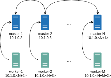
Where all controlplane nodes will be used as Wireguard servers which listen on port 51111.
All controlplanes and workers will connect to all controlplanes.
It also sets PersistentKeepalive to 5 seconds to establish controlplanes to workers connection.
After the cluster is deployed it should be possible to verify Wireguard network connectivity.
It is possible to deploy a container with hostNetwork enabled, then do kubectl exec <container> /bin/bash and either do:
ping 10.1.0.2
Or install wireguard-tools package and run:
wg show
Wireguard show should output something like this:
interface: wg0
  public key: OMhgEvNIaEN7zeCLijRh4c+0Hwh3erjknzdyvVlrkGM=
  private key: (hidden)
  listening port: 47946

peer: 1EsxUygZo8/URWs18tqB5FW2cLVlaTA+lUisKIf8nh4=
  endpoint: 10.5.0.2:51111
  allowed ips: 10.1.0.0/24
  latest handshake: 1 minute, 55 seconds ago
  transfer: 3.17 KiB received, 3.55 KiB sent
  persistent keepalive: every 5 seconds
It is also possible to use generated configuration as a reference by pulling generated config files using:
talosctl read -n 10.5.0.2 /system/state/config.yaml > controlplane.yaml
talosctl read -n 10.5.0.3 /system/state/config.yaml > worker.yaml
Manual Configuration
All Wireguard configuration can be done by changing Talos machine config files. As an example we will use this official Wireguard quick start tutorial.
Key Generation
This part is exactly the same:
wg genkey | tee privatekey | wg pubkey > publickey
Setting up Device
Inline comments show relations between configs and wg quickstart tutorial commands:
...
network:
  interfaces:
    ...
      # ip link add dev wg0 type wireguard
    - interface: wg0
      mtu: 1500
      # ip address add dev wg0 192.168.2.1/24
      addresses:
        - 192.168.2.1/24
      # wg set wg0 listen-port 51820 private-key /path/to/private-key peer ABCDEF... allowed-ips 192.168.88.0/24 endpoint 209.202.254.14:8172
      wireguard:
        privateKey: <privatekey file contents>
        listenPort: 51820
        peers:
          allowedIPs:
            - 192.168.88.0/24
          endpoint: 209.202.254.14.8172
          publicKey: ABCDEF...
...
When networkd gets this configuration it will create the device, configure it and will bring it up (equivalent to ip link set up dev wg0).
All supported config parameters are described in the Machine Config Reference.